Block Generation: Densify and Octree
The Densify operation subdivides blocks into multiple blocks, allowing the user to more finely discretize a coarse mesh in an area of particular interest.
Combining Geometry-based filtering with Densification can be done to produce Octree meshes.
Densifying Grids
The block densify command is used to generate a simple block assembly and then densify the grid. The block densify command executes, effectively, a set of block cut commands to split the blocks according to input parameters. Therefore, new blocks will inherit groups from their parent blocks as they do when a block cut command is executed. And as with block cut, the block densify command cannot be used after blocks have been zoned.
The block densify command works by calculating the extent of the block in the \(x\)-, \(y\)- and \(z\)-directions. It then calculates the locations for cuts based on the number of segments specified in each direction. By default, block densify assumes two segments in each direction. Therefore, a cut will be made halfway between the minimum and maximum \(x\), halfway between the minimum and maximum \(y\), and halfway between the minimum and maximum \(z\). The following example shows how to create and densify a wedge-shaped block. The original block and the densified blocks are shown in Figure 1 and Figure 2, respectively.
model new
block create prism face-1 (0 0 0) (4 0 0) (0 0 4) ...
  face-2 (0 4 0) (4 4 0) (0 4 4)

block densify
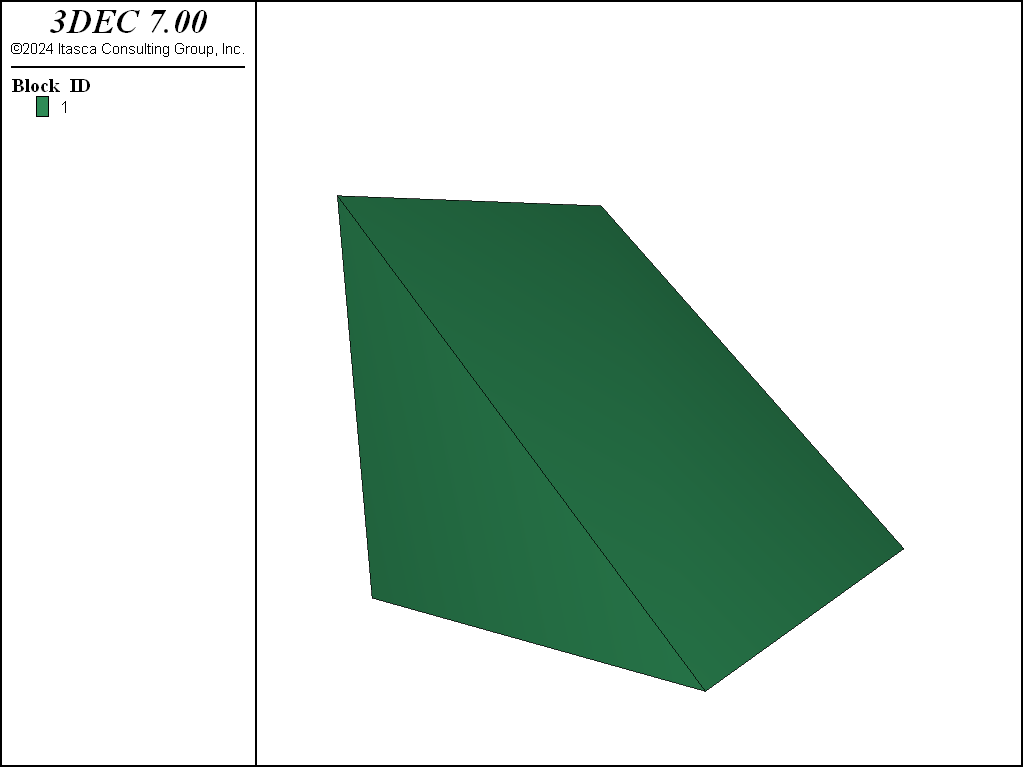
Figure 1: Original block.
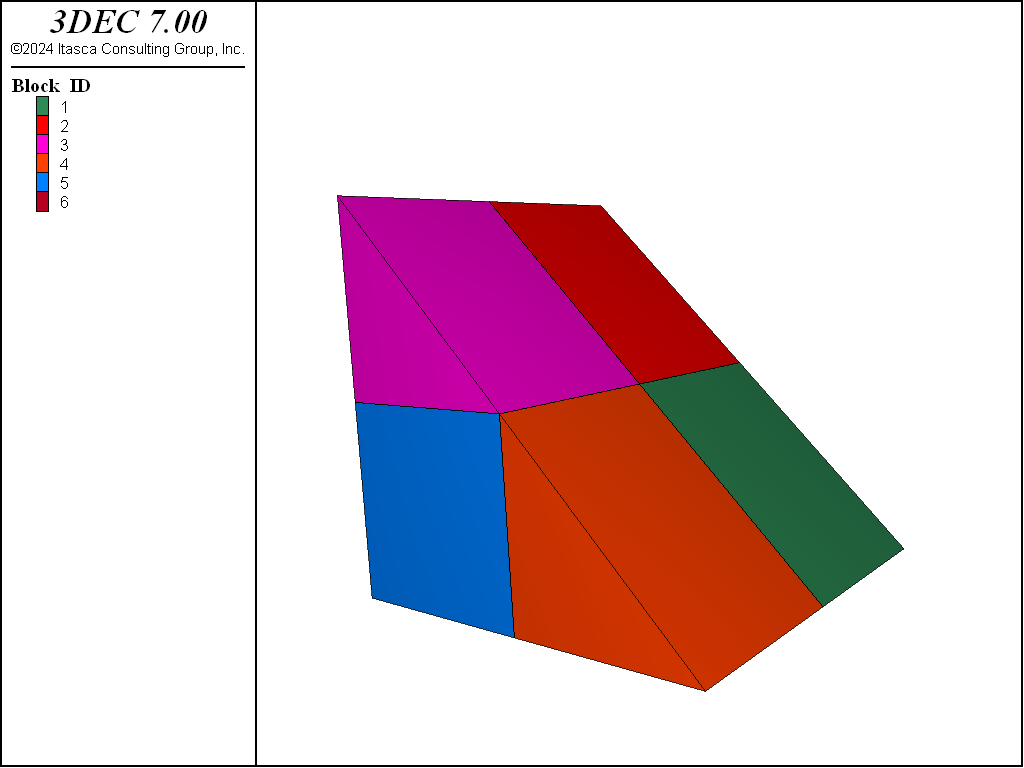
Figure 2: Block densified by dividing into two segments in each direction.
Note
If all of the blocks being densified are hexahedra, use the hex keyword with the block densify for significantly faster densification. Note that the join keyword does not work if the hex keyword is in use.
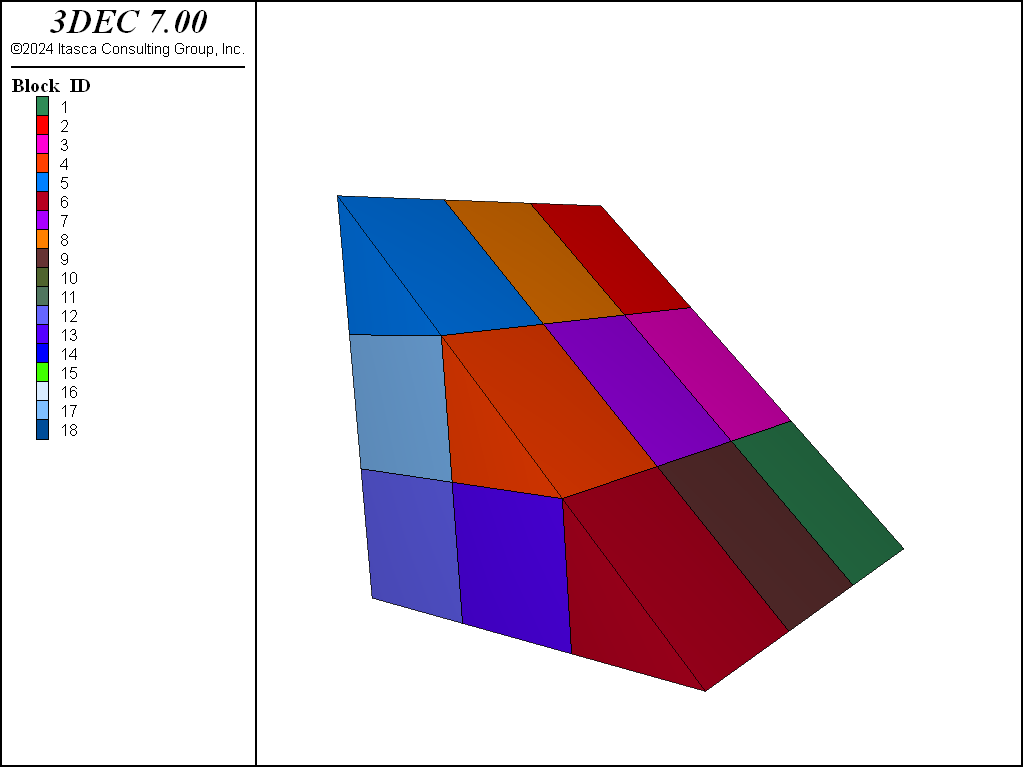
The number of segments in each direction is given by the optional segment keyword. The segment keyword is followed by three numbers: the number of segments in the \(x\)-, \(y\)- and \(z\)-directions. If only one number is given, it is assumed that \(y\) and \(z\) are the same as \(x\). In the above example, replace the command block densify with block densify segments 3. The resulting blocks are shown in Figure 3.
In addition to dividing the segments, specifying the maximum length of the refining zones is done using the maximum-length keyword. No matter how maximum-length or segments is used, 3DEC always densifies the grid by dividing the block edges with a segment number of an integer. The next example shows how to densify a grid in the range of \(z\)-coordinates between 2 and 4 by setting the edge limit to be 0.15.
; densify a block by specifying the maximum size length
model new
block create brick 0 4 0 4 0 4
block densify segments 4
block densify maximum-length 0.15 hex range position-z 2 4
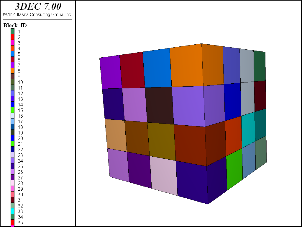
Figure 4: Original grid.
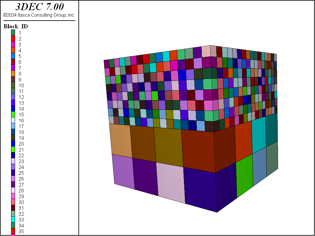
Figure 5: Densified model by setting the maximum lengths.
Figure 5 shows that sometimes densification produces a situation where small blocks are adjacent to much larger blocks. Generally it is recommended that adjacent blocks do not vary significantly in size, to maintain accuracy in the calculations. This can be resolved using the gradient-limit keyword. The gradient-limit keyword ensures that adjacent blocks do not differ by more than one level of densification. If the gradient-limit keyword is added to the block densify command in the above example, blocks are generated as shown in Figure 5.
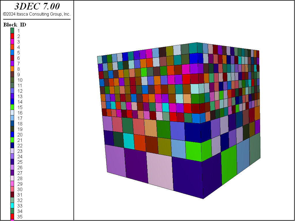
Figure 6: Densified model using the gradient-limit keyword.
There is a special case of densification in which the blocks to be densified are tetrahedra (four-sided). Models imported from Griddle, or other meshing software, may be predominantly tetrahedral. Densifying these with the methods described above can result in blocks with poor block geometries.
Figure 7 shows the result of the default densification on a simple tetrahedral block. This example shows densification resulting in blocks of drastically different sizes. To create better blocks, add the keyword tet to the block densify command. When this keyword is invoked, the blocks are not cut along the \(x\)-, \(y\)- and \(z\)-directions. Instead, each tetrahedral block is split into eight smaller tetrahedra. The number of blocks resulting from either approach is the same (eight) but the block geometry is much better when the tet keyword is used, as shown in Figure 8.
model new
block create tetrahedron (0 0 0) (.5 -.5 0) (1 0.5 0) (0.35 0.25 0.5)
block densify tet
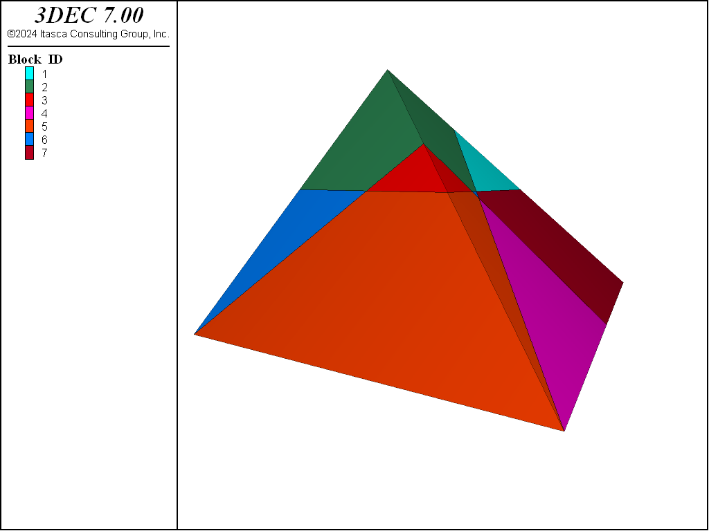
Figure 7: A densified tetrahedral block.
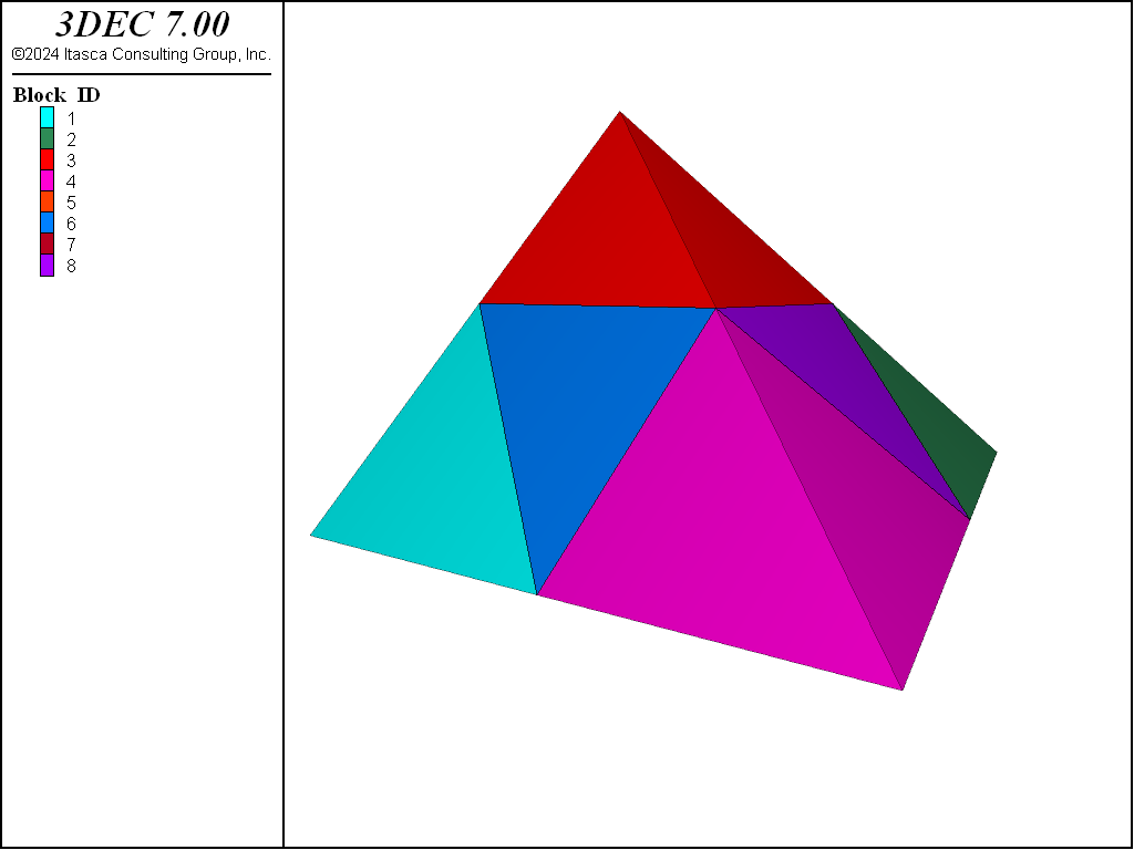
Figure 8: A densified tetrahedral block using the tet keyword.
Densifying the grid can be done using geometric sets. The next example presents a method to densify a space between two geometric sets. See i Working with Geometric Data for a general overview and description of using geometric data to identify objects in the model.
In this example, each geometric set is defined by two polygons. The block densify command
uses a geometry range element that selects any blocks with a centroid such that a ray
with direction of (0,0,1) will intersect once with any of the polygons making up setA or
setB. See the range geometry-space documentation for details.
The next two figures plot the original and densified grids.
; Densify a model using geometric information
model new
block create brick 0 10 0 10 0 10
geometry select 'setA'
geometry polygon create by-position 0 0 1 5 0 1 5 10 1 0 10 1
geometry select 'setA'
geometry polygon create by-position 5 0 1 10 0 5 10 10 5 5 10 1
geometry select 'setB'
geometry polygon create by-position 0 0 5 5 0 5 5 10 5 0 10 5
geometry select 'setB'
geometry polygon create by-position 5 0 5 10 0 10 10 10 10 5 10 5
;
block densify segments 10 join
block densify hex range geometry-space 'setA' set 'setB' count 1
;
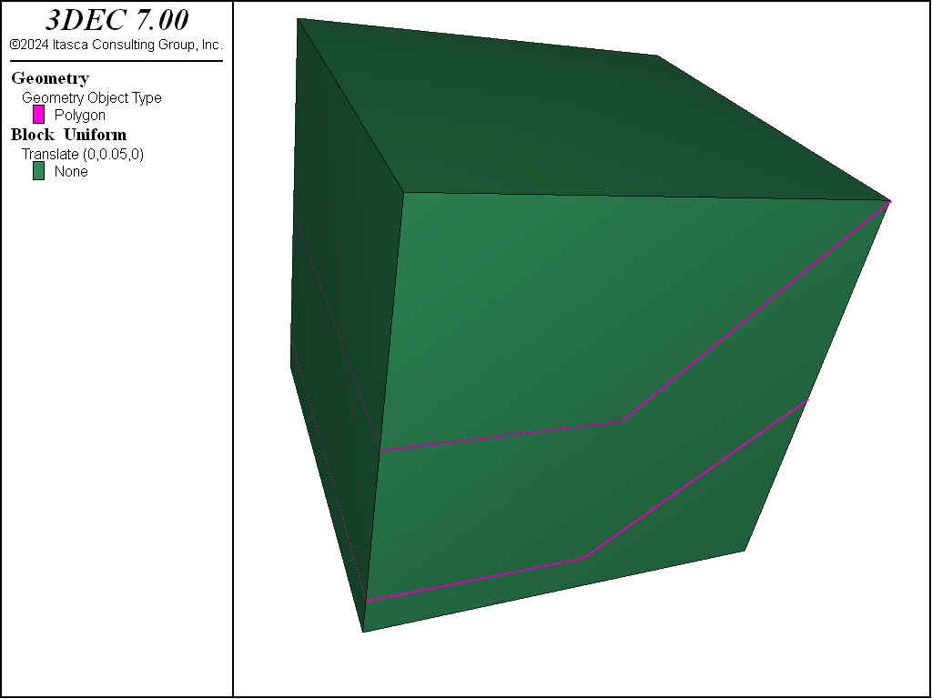
Figure 9: Original grid.
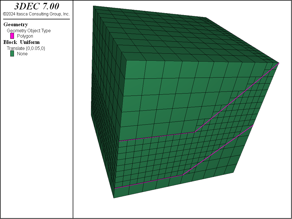
Figure 10: Densified grid using geometric data.
Geometry-Based Densification: Octree Meshing
Grid densification based on geometric data in geometric sets is often used to approximate material property changes on a very irregular boundary, when exact conformation to the surface is not important physically. Often orebody and other kinds of geologic structures fall into this category.
The command block densify can be used to subdivide blocks selected by their proximity to a
geometry surface. Using it in combination with the range geometry-distance range element
and using the repeat keyword allows the creation of an octree mesh in a single command.
For example, the command
block densify maximum-length 50 gradient-limit repeat hex ...
    range geometry-distance 'topo' gap 0 extent
can be used to generate an octree mesh based on proximity to the “topo” geometry set.
It is important to be clear about what each of the keywords invoked above is doing.
- The gradient-limit keyword affects the blocks tagged for densification. It ensures that the maximum difference in block size from one block to the next is one level of densification.
- The maximum-length keyword in combination with repeat (described below) indicates that blocks will be tagged for densification if they have an edge length longer than 50.
- The repeat keyword indicates that a single densification pass will be made over the blocks. Then, if any blocks were densified, a new list of blocks will be selected for densification. This operation will be repeated until no blocks are left to be densified, either because they do not fall within the range or because they are already smaller than the maximum-length specified. (Note that if the
repeatkeyword is omitted in this example, the densification occurs in a single step and thegradient-limitkeyword is ignored.) - The hex keyword tells 3DEC that all of the blocks being densified are hexahedra. This enables a faster algorithm to be used for densification.
- The
range geometry-distanceselects blocks that fall within a gap distance from the topo geometry set. Since the gap is zero in this case, it selects blocks that actually intersect the surface. - The extent keyword indicates that the distance from the surface should be judged by the Cartesian extent of the block, rather than the block centroid. If this was not used, a non-zero gap would be required to allow any chance of a block falling within the range.
Note that the segments keyword is not provided. If the number of segments is not specified, it is assumed to be 2 in each direction, resulting in eight new blocks for every original.
The blocks above the topography are then hidden using the command:
block hide range geometry-space 'topo' direction (0,0,-1) count 1
This range will project a ray from each block centroid in the specified direction and count the number of intersections with the geometric surface. If the count = 1, the block is selected for hiding. The results of these commands are shown here.
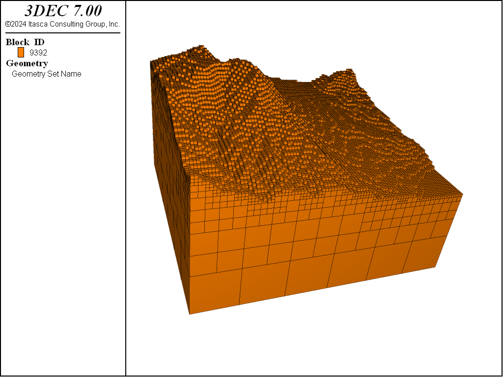
Figure 11: Octree mesh generated with block densify.
Probably it is desirable to execute the block join command after this densification, since the joints between the blocks do not represent real joints or faults.
For a more realistic example, the following data file takes a simple rectangular mesh and uses it as a starting point to create an octree mesh of a complex orebody.
model new
block create brick 25000 35000 20000 35000 0 10000

block densify segments 10 15 10 hex

geometry import 'orebody.stl'
block densify gradient-limit maximum-length 50 repeat hex ...
             range geometry-distance 'orebody' gap 0.0 extent

block group 'orebody' range geometry-space 'orebody' count odd
The result of that operation is shown in the figure below. The last block group command uses the range geometry-space range element to select blocks “inside” the geometric surface. If a direction is not given with the geometry-space range, it is assumed to be upwards (0,0,1).
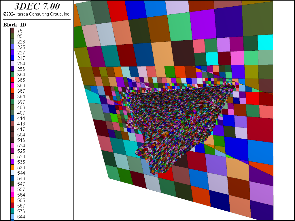
Figure 12: Octree mesh generated with block densify.
| Was this helpful? ... | 3DEC © 2019, Itasca | Updated: Feb 25, 2024 |