Isotropic Rectangular Plate with Applied Pressure
Problem Statement
Note
To view this project in FLAC3D, use the menu command . Choose “Structure/Shell/PlateAppliedPressure” and select “PlateAppliedPressure.prj” to load. The main data files used are shown at the end of this example. The remaining data files can be found in the project.
An isotropic rectangular plate (4 m by 8 m) is simply supported along its edges. The solution for bending and deflection of the plate when subjected to a uniform pressure, p, is given by Ugural (1981, pp. 66-73). The maximum deflection, wmax, occurs at the plate center and equals
The maximum bending stress resultants also occur at the plate center and equal
| where: | a | = | short length of plate; |
| D | = | flexural rigidity = Et312(1−ν2) (E is Young’s modulus=, ν is Poisson’s ratio, and t, is plate thickness); and | |
| δ1,δ2,δ3 | = | coefficients from Table 3.1 of Ugural (1981) (δ1 = 0.01013, δ2 = 0.1017, δ3 = 0.0464). |
The following shell properties are specified:
| thickness (t) | 0.3 m |
| Young’s modulus (E) | 30 GPa |
| Poisson’s ratio (ν) | 0.30 |
For an applied pressure of 240 kPa, the plate oriented such that a = 4 m (aligned with the y-axis), and the long dimension of the plate aligned with the x-axis, the maximum plate deflection is wmax = 8.39 mm, and the maximum bending stress resultants are Mx = 178 kN and My = 391 kN (where the surface coordinate system in which Mx and My are expressed is aligned with the global system).
The FLAC3D model consists of 64 shell elements, as shown in Figure 1.
Only half of the plate is modeled; a symmetry plane is prescribed at half the long dimension (at
x = 4). The nodes along the symmetry edge have their x-velocities and y- and
z-rotations fixed. The other three edges have only their z-velocities fixed to
simulate simple supports. (Although the proper classical plate theory boundary condition for a
simple support also includes constraining rotation about an axis in the plane of the plate directed
normal to the edge, such classical boundary conditions tend to overconstrain the mesh and produce
results that are too stiff (Cook 1989, p. 332).) The pressure loading is applied with the
structure shell apply command. A cross-diagonal mesh pattern is utilized to ensure symmetric
response, and the DKT Plate Bending Element is also utilized. The same
results would be produced if either of the shell finite elements were used, because no membrane
loading occurs.
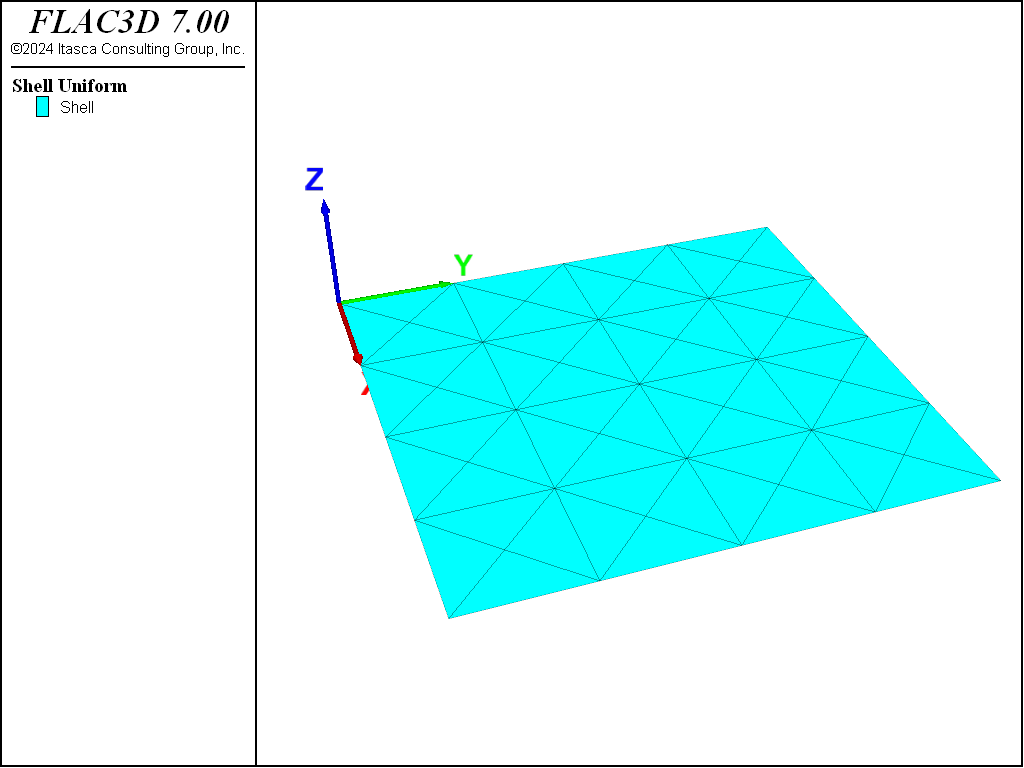
Figure 1: FLAC3D model for rectangular plate problem.
The displacement field is shown in Figure 3 and Figure 2. The maximum plate deflection occurs at the plate center and equals 8.224 mm, which is within 2% of the theoretical value.
Contours of the bending stress resultants Mx and My are shown in Figure 4 and Figure 5. The exact values computed at the plate center of Mx and My are 182 kN and 396 kN, respectively, which are both within 2.3% of the analytical values.
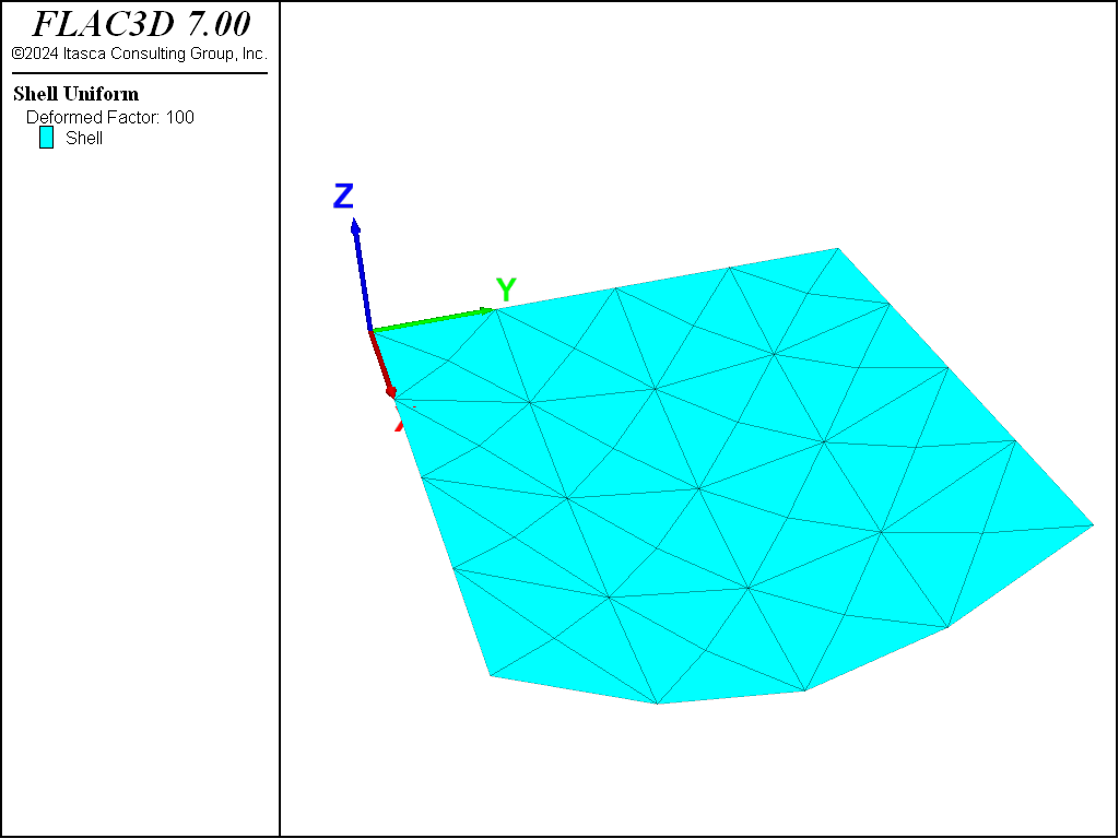
Figure 2: Deformed (magnification of 100) shape of rectangular plate.
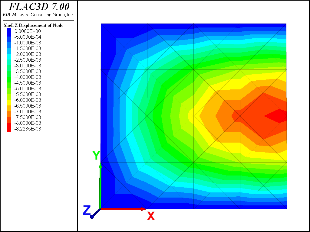
Figure 3: Contours of plate deflection.
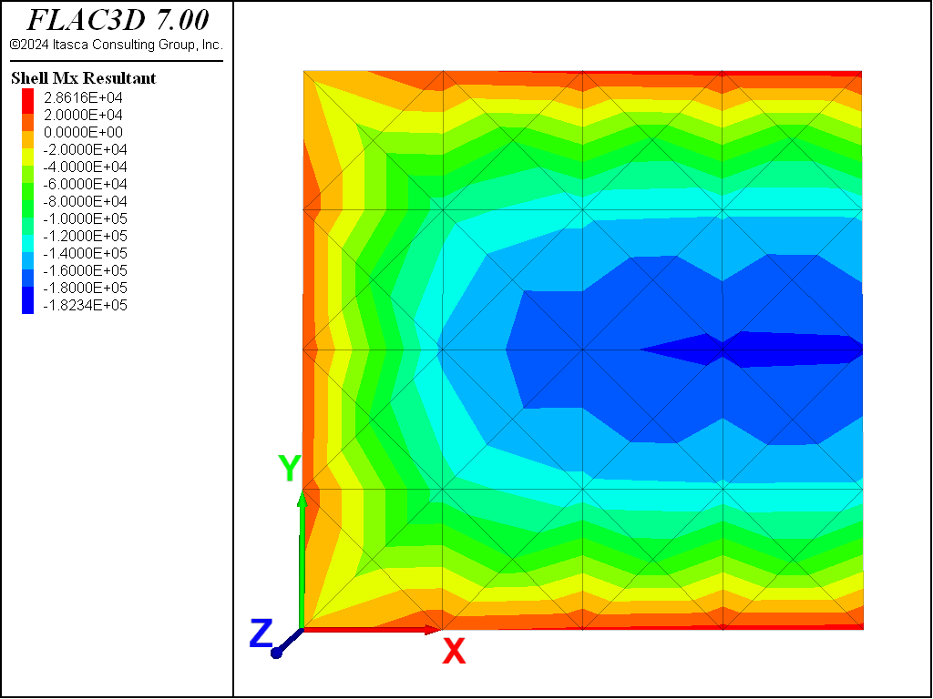
Figure 4: Contour of bending stress resultant Mx.
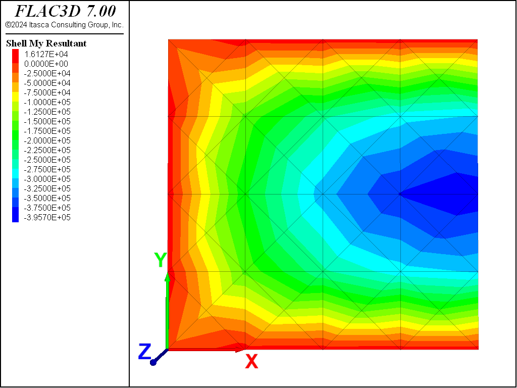
Figure 5: Contour of bending stress resultant My.
References
Cook, R. D., D. S. Malkus and M. E. Plesha. Concepts and Applications of Finite Element Analysis, Third Edition. New York: John Wiley & Sons Inc. (1989).
Ugural, A. C. Stresses in Plates and Shells. New York: McGraw-Hill Publishing Company Inc. (1981).
Data File
PlateAppliedPressure.dat
model new
model large-strain off
model title "Rectangular plate with applied pressure"
; Create shell elements and set properties
struct shell create by-quadrilateral (0,0,0) (4,0,0) (4,4,0) (0,4,0) ...
                    size (4,4) element-type=dkt cross-diagonal
struct shell property isotropic=(30e9, 0.3) thick=0.3
; Bounday conditions
struct node fix velocity-z range position-y 4 ; Simply supported condition
struct node fix velocity-z range position-x 0
struct node fix velocity-z range position-y 0
struct node fix velocity-x rotation-y rotation-z range position-x 4
; Symmetry condition
; Applied Pressure
struct shell apply -240e3
; Solve
model solve ratio-local=1e-6
model save 'PlateAppliedPressure'
⇐ Plastic Hinge Formation in a Shell Structure | Advancing Lined Tunnel (Rigidly Connected to Zones) ⇒
| Was this helpful? ... | 3DEC © 2019, Itasca | Updated: Feb 25, 2024 |