Steady-State Fluid Flow with a Free Surface
Note
The project file for this example is available to be viewed/run in FLAC3D.[1] The project’s main data files are shown at the end of this example.
This example is the classical problem of steady-state seepage flow through a homogeneous embankment with vertical slopes exposed to different water levels and resting on an impermeable base. The total discharge, \(Q\), and the length of seepage face, \(s\), are compared to the exact solutions. Figure 1 shows the geometry and boundary conditions of the problem.
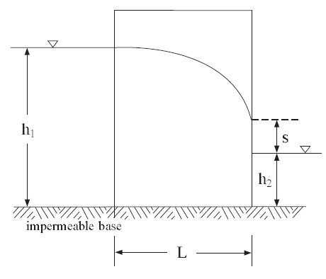
Figure 1: Problem geometry and boundary conditions.
The fluid is homogeneous, flow is governed by Darcy’s law, and it is assumed that the pores of the soil beneath the phreatic surface are completely filled with water and the pores above it are completely filled with air. The width of the dam is \(L\), the head and tail water elevations above the impervious base are \(h_{1}\) and \(h_{2}\), respectively.
The exact solution for the total discharge through a dam section of unit thickness was shown by Charny (Harr 1991) to be given by Dupuit’s formula:
where \(k\) is mobility coefficient, \(\rho _{w}\) is water density and \(g\) is gravity. The length, \(s\), of the seepage face (elevation of the free surface on the downstream face of the dam above \(h_{2}\)) was obtained by Polubarinova-Kochina (1962), and is given in Figure 2 as a function of the characteristic dimensions of the problem.
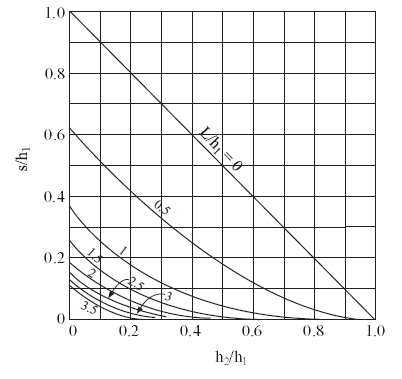
Figure 2: Seepage face solution after Polubarinova-Kochina (1962).
The FLAC3D simulation is conducted for a particular set of parameters:
| L | = | 9 m |
| h1 | = | 6 m |
| h2 | = | 1.2 m |
Several material properties are used:
| permeability (\(k\)) | 10-10 (m/sec)(Pa/m) |
| porosity (\(n\)) | 0.3 |
| water density (\(\rho_w\)) | 1000 kg/m3 |
| water bulk modulus (\(K_f\)) | 1000 Pa |
| soil dry density (\(\rho\)) | 2000 kg/m3 |
| gravity (\(g\)) | 10 m/sec2 |
Two cases corresponding to two different initial conditions have been studied:
| CASE 1: | The water level in the embankment is initially at \(h\) = \(h_2\) = 1.2 m. The upstream level is raised to \(h\) = \(h_1\). |
| CASE 2: | The water level is initially at \(h\) = \(h_1\) = 6 m. The downstream level is lowered to \(h\) = \(h_2\). |
The data file for Case 1 is listed in “FreeSurfaceSteadyStateFluidFlow-Case1.dat”, and in “FreeSurfaceSteadyStateFluidFlow-Case2.dat” for Case 2. The grid and boundary conditions are the same for both cases. The grid contains 30 zones in width, 20 zones in height, and 1 zone in thickness. The boundary conditions correspond to a static pore-pressure distribution up to level \(h_{1}\) on the upstream face, and up to \(h_{2}\) on the downstream face, zero pore pressure from level \(h_{2}\) to \(h_{1}\) on the downstream face, and to no-flow conditions across the remaining boundaries. The differences between the two cases are the initial pore pressure and saturation distributions. In Case 1, saturation and pore pressure are zero above \(h_2\). Below that level, the saturation is 1 and the pressure is hydrostatic. In Case 2, saturation is 1 for all gridpoints, and the pore pressure inside the mesh follows a gravitational gradient. The numerical simulation is carried out until steady-state conditions are detected.
To speed the calculation to steady state, the water bulk modulus is given a small value (\(K_{f}\) = 103 Pa) compatible with free surface stability. (The criterion used is \(K_{f}\geq 0.3\rho _{w}gL_{z}\), where \(L_{z}\) is the maximum vertical zone dimension in the vicinity of the phreatic surface, as discussed in Time Scales.)
The final flow pattern is similar for both initial conditions (see Figure 3 and Figure 4). The numerical value of seepage length is defined as the distance on the downstream face of the dam, between the tail water elevation and the point where the magnitude of the flow vector vanishes. The analytical value of seepage length is determined from Figure 2. For this particular problem, \(h_{2}/h_{1}\) = 0.2, \(L/h_{1}\) = 1.5, and the value of \(s/h_{1}\) is thus 0.1. As seen in the figures, the numerical value of seepage length compares well with the analytical solution sketched there as a bold line. A FISH function, qflac, is used to determine the discharge, \(Q\), per unit thickness of the dam: the steady-state numerical value is 1.914 × 10⁻⁶m2/s for Case 1; and 1.912 × 10⁻⁶m2/s for Case 2. The values are close to the analytic value of 1.920 × 10⁻⁶m2/s, as determined from Equation (1) for this particular problem.

Figure 3: Steady-state flow vectors and seepage face solution—Case 1.
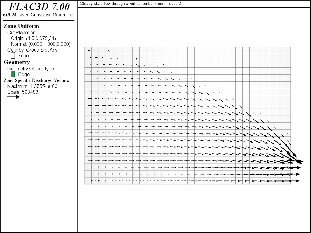
Figure 4: Steady-state flow vectors and seepage face solution—Case 2.
Case 1 is repeated to test fluid flow across two sub-grids that are connected by using either the
zone attach command or the zone interface create command.
“FreeSurfaceSteadyStateFluidFlow-Case1-Attach.dat” lists the commands for flow across an attached grid,
and “FreeSurfaceSteadyStateFluidFlow-Case1-Interface.dat” lists the commands for flow across an interface.
Both model results are nearly identical to the original Case 1; the values for discharge for both the
Attach and Interface models are 1.924 × 10⁻⁶m2/s and 1.913 × 10⁻⁶m2/s, respectively. Compare Figure 5 and
Figure 6 to Figure 3.
Note that if maximum-edge is specified with the zone interface element command,
then the interface will act as an impermeable boundary. Remove the semicolon from the line of
zone.interface.1.element.maximum-edge to observe this response.
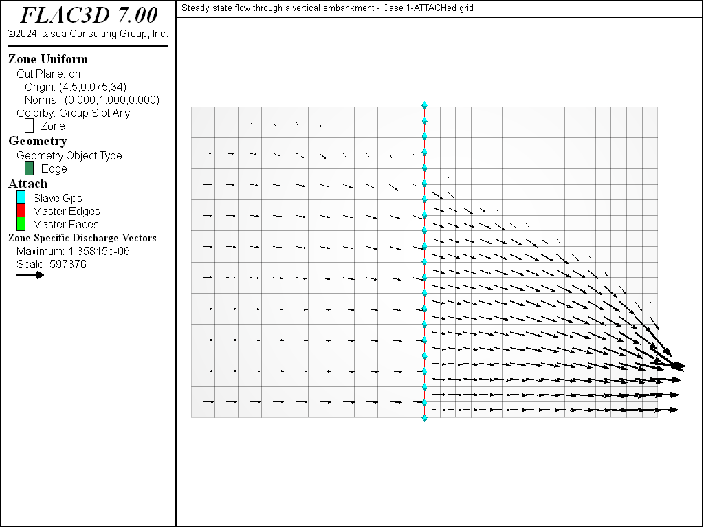
Figure 5: Steady-state flow vectors for attached grid—Case 1.
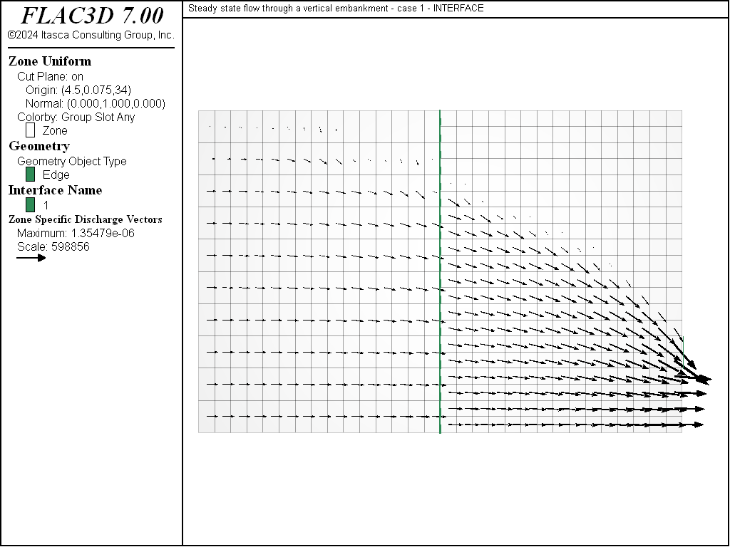
Figure 6: Steady-state flow vectors for grid with an interface—Case 1.
Reference
Harr, M. E. Groundwater and Seepage. Dover (1991).
Data Files
FreeSurfaceSteadyStateFluidFlow-Case1.dat
model new
model large-strain off
model title "Steady state flow through a vertical embankment - case 1"
program call 'fishFunctions'
model configure fluid
zone create brick size 30 1 20 point 1 (9.0,0,0) point 2 (0,0.15,0) ...
                               point 3 (0,0,6.0)
; --- fluid flow model ---
zone fluid cmodel assign isotropic
zone fluid property permeability 1e-10 porosity 0.3
zone fluid biot off
zone gridpoint initialize fluid-modulus 1e3
zone gridpoint initialize saturation 0.0
zone gridpoint initialize saturation 1.0 ...
                          range union position-x 0 position-z 0.0 1.19
zone gridpoint initialize pore-pressure 1.2e4 grad (0,0,-1e4) ...
                          range position-z 0.0 1.19
zone face apply pore-pressure 6.0e4 grad 0 0 -1e4 ...
                              range position-x 0.0
zone face apply pore-pressure 1.2e4 grad 0 0 -1e4 ...
                              range position-x 9.0 position-z 0.0 1.19
zone face apply pore-pressure 0.0 ...
                              range position-x 9.0 position-z 1.2 6.0
; Add particle tracks
zone fluid track create line begin (0,0.1,0.5) end (0,0.1,5.5) ...
                             segment 12 group "set1"
zone fluid track active on
; --- settings ---
zone initialize fluid-density 1e3
zone gridpoint initialize fluid-tension 0.0
model gravity 0 0 -10
model mechanical active off
model fluid active on
; --- test ---
model solve ratio-flow 1.e-3
[show_seepage_face]
fish list [qflac] [qsol]
model save 'ch2a'
FreeSurfaceSteadyStateFluidFlow-Case2.dat
model new
model large-strain off
model title "Steady state flow through a vertical embankment - case 2"
program call 'fishFunctions'
model configure fluid
zone create brick size 30 1 20 point 1 (9.0,0,0) point 2 (0,0.15,0) ...
                               point 3 (0,0,6.0)
; --- fluid flow model ---
zone fluid cmodel assign isotropic
zone fluid property permeability 1e-10 porosity 0.3
zone fluid biot off
zone gridpoint initialize fluid-modulus 1e3
zone gridpoint initialize saturation 1.0
zone gridpoint initialize saturation 0.0 ...
                          range position (0.01,0,5.99) (6.0,0.15,6.0)
zone gridpoint initialize pore-pressure 6.0e4 grad (0,0,-1e4) ...
                          range position-z 0.0 6.0
zone face apply pore-pressure 6.0e4 grad 0 0 -1e4 ...
                              range position-x 0.0
zone face apply pore-pressure 1.2e4 grad 0 0 -1e4 ...
                              range position (9.0,0,0) (9.0,0.15,1.19)
zone face apply pore-pressure 0.0 ...
                              range position (9.0,0,1.2) (9.0,0.15,6.0)
; --- settings ---
zone initialize fluid-density 1e3
zone gridpoint initialize fluid-tension 0.0
model gravity 0 0 -10
model mechanical active off
model fluid active on
; --- test ---
model solve ratio-flow 1e-3
[show_seepage_face]
fish list [qflac] [qsol]
model save 'ch2b'
FreeSurfaceSteadyStateFluidFlow-Case1-Attach.dat
model new
model large-strain off
model title ...
     "Steady state flow through a vertical embankment - Case 1-ATTACHed grid"
model configure fluid
program call 'fishFunctions'
zone create brick size 10 1 10 point 0 (0,0,0)      point 1 (4.5,0,0) ...
                               point 2 (0,0.15,0)   point 3 (0,0,6)
zone create brick size 15 1 20 point 0 (4.5,0,0)    point 1 (9,0,0)   ...
                               point 2 (4.5,0.15,0) point 3 (4.5,0,6) merge off
zone attach by-face
; --- fluid flow model ---
zone fluid cmodel assign isotropic
zone fluid property permeability 1e-10 porosity 0.3
zone fluid biot on
zone gridpoint initialize biot 3.333e3
zone gridpoint initialize saturation 0.0
zone gridpoint initialize saturation 1.0 ...
                          range union position-x 0 position-z 0.0 1.19
zone gridpoint initialize pore-pressure 1.2e4 grad (0,0,-1e4) ...
                          range position-z 0.0 1.19
zone face apply pore-pressure 6.0e4 grad 0 0 -1e4 ...
                range position-x 0.0
zone face apply pore-pressure 1.2e4 grad 0 0 -1e4 ...
                range position-x 9.0 position-z 0.0 1.19
zone face apply pore-pressure 0.0 ...
                range position-x 9.0 position-z 1.2 6.0
; --- settings ---
zone initialize fluid-density 1e3
zone gridpoint initialize fluid-tension 0.0
model gravity 0 0 -10
model mechanical active off
model fluid active on
; --- test ---
model solve ratio-flow 1.e-3
[show_seepage_face]
fish list [qflac] [qsol]
model save 'attfl'
FreeSurfaceSteadyStateFluidFlow-Case1-Interface.dat
model new
model large-strain off
model title ...
      "Steady state flow through a vertical embankment - case 1 - INTERFACE"
model configure fluid
program call 'fishFunctions'
zone create brick size 15 1 10 point 0 (0,0,0)    point 1 (4.5,0,0) ...
                               point 2 (0,0.15,0) point 3 (0,0,6) ...
                               group 'Left'
zone create brick size 15 1 20 point 0 (5.5,0,0)  point 1 (10,0,0) ...
                               point 2 (5.5,0.15,0) point 3 (5.5,0,6) ...
                               group 'Right'
; --- interface ---
zone interface create by-face range position-x 5.5
zone interface node property stiffness-shear 2e9 stiffness-normal 2e9 ...
                             friction 15 tension 1e10
; zone interface element maximum-edge 1 ; <=== will make interface impermeable
zone gridpoint initialize position-x -1.0 add range group 'right'
; --- fluid flow model ---
zone fluid cmodel assign isotropic
zone fluid property permeability 1e-10 poros 0.3
zone fluid biot on
zone gridpoint initialize biot 3.333e3
zone gridpoint initialize saturation 0.0
zone gridpoint initialize saturation 1.0 ...
                          range union position-x 0 position-z 0.0 1.19
zone gridpoint initialize pore-pressure 1.2e4 grad (0,0,-1e4) ...
                          range position-z 0.0 1.19
zone face apply pore-pressure 6.0e4 grad 0 0 -1e4 ...
                range position-x 0.0
zone face apply pore-pressure 1.2e4 grad 0 0 -1e4 ...
                range position-x 9.0 position-z 0.0 1.19
zone face apply pore-pressure 0.0 ...
                range position-x 9.0 position-z 1.2 6.0
; --- mechanical model ---
zone cmodel assign elastic
zone property bulk 2 shear 1
model cycle 0 ; <--- to initialize weighting factors
; --- settings ---
zone initialize fluid-density 1e3
zone gridpoint initialize fluid-tension 0.0
model gravity 0 0 -10
model mechanical active off
model fluid active on
; --- test ---
model solve ratio-flow 1.e-3
[show_seepage_face]
fish list [qflac] [qsol]
model save 'intfl'
Endnotes
| [1] | To view this project in FLAC3D, use the program menu.
⮡ FLAC |
| Was this helpful? ... | 3DEC © 2019, Itasca | Updated: Feb 25, 2024 |