Smooth Square Footing on a Cohesive Frictionless Material
Problem Statement
Note
The project file for this example is available to be viewed/run in FLAC3D.[1] The main data file used is shown at the end of this example. The remaining data files can be found in the project.
This problem is concerned with the numerical determination of the bearing capacity of a smooth rectangular footing on a cohesive frictionless material (Tresca model).
The footing of width 2\(a\) and length 2\(b\) is located on an elasto-plastic Tresca material with the following properties:
| shear modulus (\(G\)) | 0.1 GPa |
| bulk modulus (\(K\)) | 0.2 GPa |
| cohesion (\(c\)) | 0.1 MPa |
| friction angle (\(\phi\)) | 0° |
| dilation angle (\(\psi\)) | 0° |
Upper- and Lower-Bound Solutions
The problem is truly three-dimensional and, although no exact solution is available, upper and lower bounds for the bearing capacity, \(q\), defined as the average footing pressure at failure, have been derived using limit analysis (see, for example, Chen 1975). The upper bound, \(q^u\), obtained using the failure mechanism of Shield and Drucker (1953), has the form
in which \(c\) is the cohesion of the material. The lower bound, \(q^l\), which corresponds to the bearing capacity of a strip footing, has the value
FLAC3D Model
In the numerical example, the footing is square and represented by an area with half-width \(a\) (and \(b\) = \(a\)). Advantage is taken of quarter symmetry, and a parallelepiped domain of 15 m × 15 m × 10 m (as sketched in the figure below) is used in the numerical simulation. The system of coordinate axes is selected with the \(x\)- and \(y\)-axes in the horizontal plane of the footing, and the \(z\)-axis pointing upward in the vertical direction.
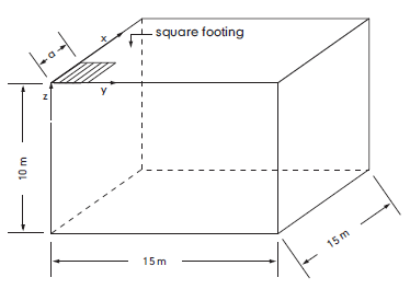
Figure 1: Domain for FLAC3D simulation—quarter symmetry.
The boundary conditions applied to this domain are sketched below:
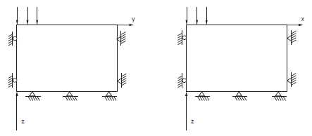
Figure 2: Boundary conditions for FLAC3D analysis—quarter symmetry.
The displacements of the far \(x\)-, \(y\)-, and \(z\)-boundaries are restricted in all directions, and the displacements of the symmetry boundaries corresponding to the planes at \(x\) = 0 and \(y\) = 0 are restricted in the \(x\)- and \(y\)-directions, respectively. The slab is smooth: displacements are free in the \(x\)- and \(y\)-directions and a velocity is applied in the negative \(z\)-direction to gridpoints within a 3 m × 3 m area to simulate loading of the footing.
The domain is discretized into 1000 zones. The area representing the footing covers a total of 3 × 3 zones. For an applied velocity loading, the bearing area is assumed to extend to half the distance between the last applied gridpoint and the next gridpoint. In this model, then, \(a\) = 3.5 m and \(b\) = 3.5 m.
The zone dimensions are graded outside the footing area according to a geometrical progression with factor 1.2 in the \(x\)-, \(y\)-, and \(z\)-directions using the Building Blocks pane (see Figure 3). The resulting commands were exported using the State pane into the data file “geometry.dat”. A velocity of magnitude 2.5 × 10⁻⁵ m/step is applied at the nodes within the footing area for a total of 7500 steps.
The FISH function load found in the file “footing-load.dat” computes the normalized average footing pressure, \(p/c\), and the corresponding relative difference with the theoretical normalized upper-bound value, \(q^u/c\) (equation (1) above).
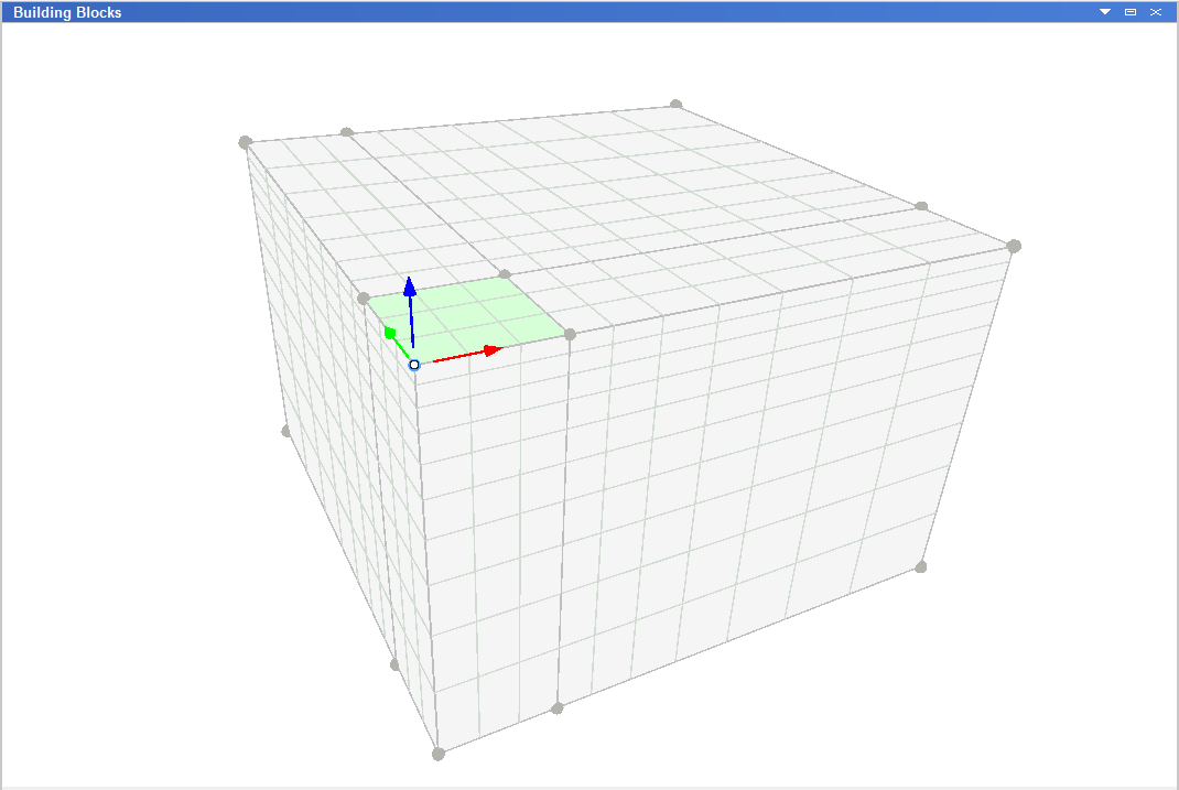
Figure 3: FLAC3D Building Blocks results—quarter symmetry.
Results and Discussion
The load-displacement curve corresponding to the numerical simulation is presented in Figure 4, in which load is the normalized average footing pressure, \(p/c\); upper and lower are the normalized upper and lower bound value for the bearing capacity, and disp is the normalized vertical displacement, \(u_z/a\), at the center of the footing. The numerical value of the bearing capacity is 526 kPa. This value is sandwiched between the theoretical upper-bound value of 571 kPa and lower-bound value of 514 kPa. The velocity field at the end of the numerical simulation is illustrated in Figure 5.
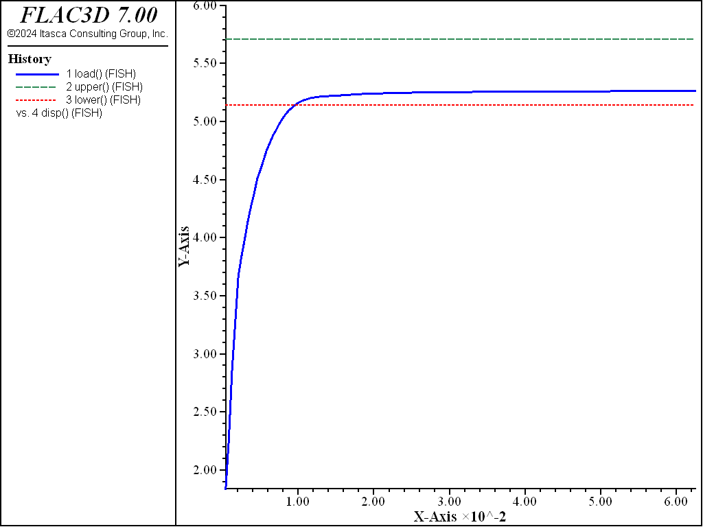
Figure 4: Load-displacement curve.
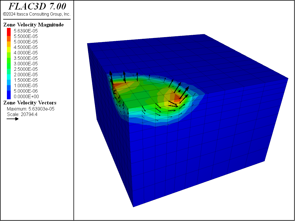
Figure 5: FLAC3D contour plot of the velocity field and velocity vectors.
The same problem was run again using FLAC3D’s nodal mixed discretization (NMD) feature (file “nmd.dat”). For this model, an all-tet grid was generating using the file “create-tet-mesh.dat”. Figure 6 and Figure 7 show the NMD results and correspond directly with Figure 4 and Figure 5 (results with an all-hex grid). As can be seen, the results are very similar.
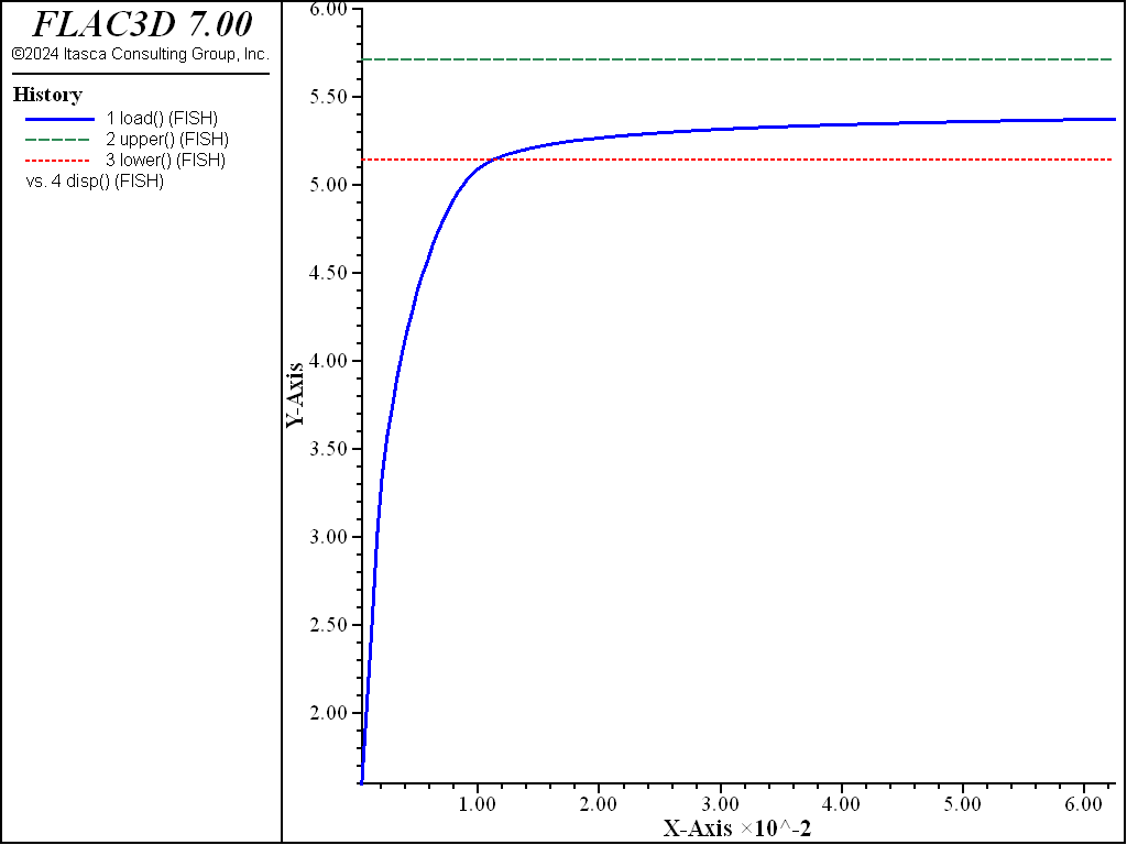
Figure 6: Load-displacement curve (NMD results).
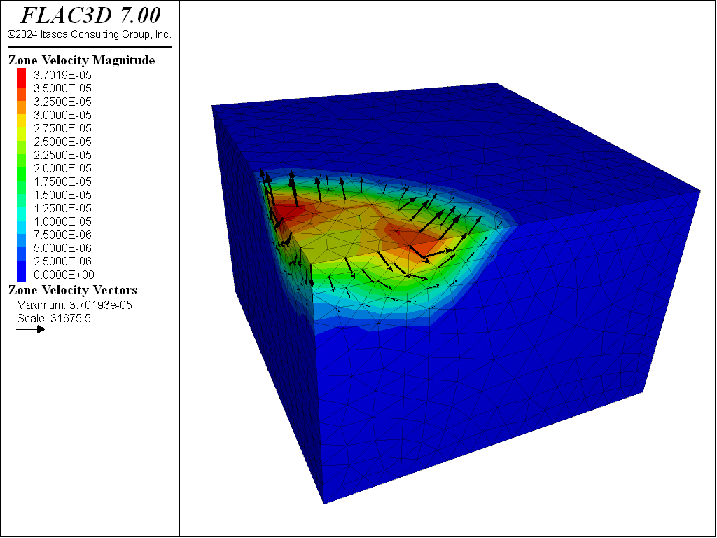
Figure 7: FLAC3D contour plot of the velocity field and velocity vectors (NMD results).
References
Chen, W.-F. “Bearing Capacity of Square, Rectangular and Circular Footings,” in Limit Analysis and Soil Plasticity, Developments in Geotechnical Engineering 7, Ch. 7, pp. 295-340, New York: Elsevier Scientific Publishing Co. (1975).
Shield, R. T., and D. C. Drucker. “The Application of Limit Analysis to Punch-Indentation Problems,” J. Appl. Mech., 20, 453-460 (1953).
Data File
SquareFooting.dat
;---------------------------------------------------------------------
; Smooth square footing on Tresca material
;             -associated plastic flow-
;---------------------------------------------------------------------
model new
model large-strain off
; Initialize parameters
[global a = 3] ; Size of footing in x and y
[global b = 3]
; load building block template geometry.f3dat created interactively
program call 'geometry'
; Make footing the size in the parameters, and create zones
building-blocks point move-to x [a] range group 'x'
building-blocks point move-to y [b] range group 'y'
zone generate from-building-blocks
; Assign constitutive models and properties
zone cmodel assign mohr-coulomb
zone property bulk 2.e8 shear 1.e8 cohesion 1.e5
zone property friction 0. dilation 0. tension 1.e10
; Boundary conditions
zone face apply velocity-normal -2.5e-5 range group 'Footing'
zone face apply velocity-normal  0.0 range position-x 0
zone face apply velocity-normal  0.0 range position-y 0
zone face apply velocity (0,0,0) ...
                range union position-x 15 position-y 15 position-z 0
; program call FISH that calculates footing load
program call 'footing-load'
; take some histories
history interval 50
fish history load
fish history upper
fish history lower
fish history disp
model history mechanical ratio-local
; Cycle till velocities stabilize
model cycle 7500
fish list [lower] [load] [upper]
fish list [errlo]
; Save the model
model save 'sslab'
Endnotes
| [1] | To view this project in FLAC3D, use the program menu.
⮡ FLAC |
⇐ Smooth Circular Footing on an Associated Mohr-Coulomb Material | Drained and Undrained Triaxial Compression Test on a Cam-Clay Sample ⇒
| Was this helpful? ... | 3DEC © 2019, Itasca | Updated: Feb 25, 2024 |