Cable-Reinforced Beam
Problem Statement
Note
To view this project in FLAC3D, use the menu command . Choose “Structure/Cable/ReinforcedBeam” and select “ReinforcedBeam.prj” to load. The main data files used are shown at the end of this example. The remaining data files can be found in the project.
This example illustrates the behavior of a simply supported, lightly reinforced beam subjected to gravity loading. Cable elements are used to represent the reinforcement.
A vertical crack is created through the beam center by adding a zero-strength interface. If the
model is run without reinforcement (by removing the structure cable create commands), the
system behaves as two separate pieces that separate at the interface. The two blocks are supported
on rollers; thus, they can move away from one another as the system collapses (see Figure 1).
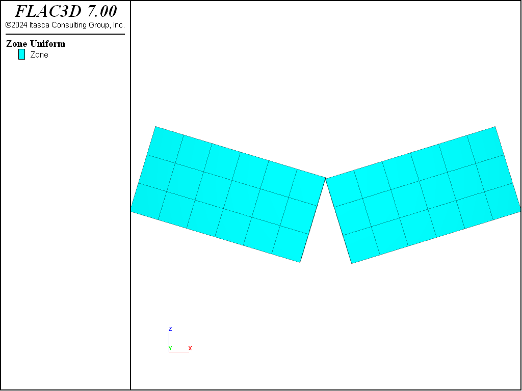
Figure 1: Structural configuration after 3000 cycles (no cable present).
If the model is rerun with a cable inserted within the beam near its bottom fiber, then the cable carries the tension that develops in the lower portion of the beam. The final axial force distribution in the cable after the model has stabilized is shown in Figure 2. These tensile forces in the cable are produced by the grout stresses that have developed along the cable length (see Figure 3). The maximum vertical center line displacement is approximately 10 mm.
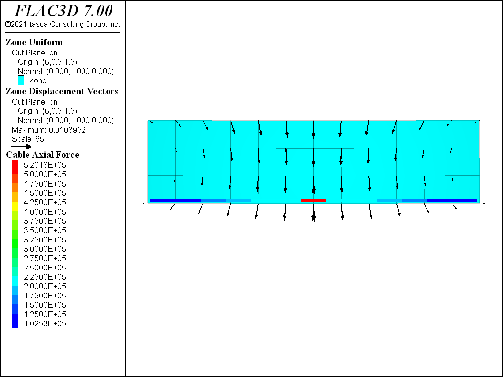
Figure 2: Final axial force distribution in cable.
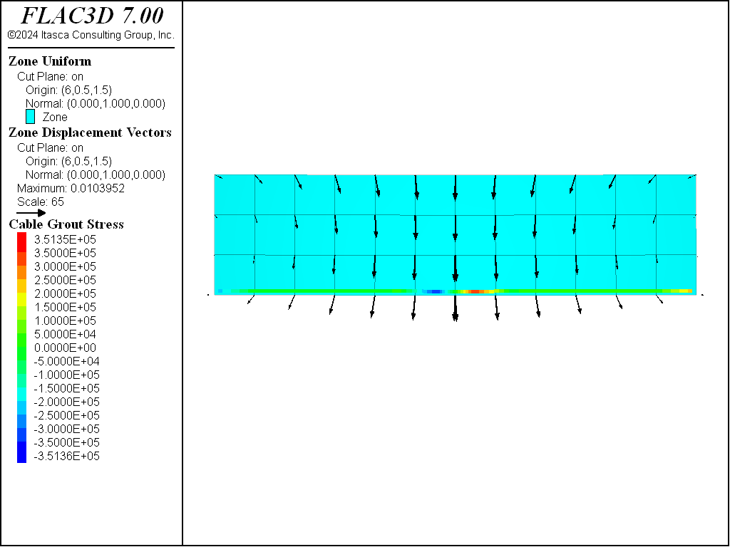
Figure 3: Final grout stress distribution.
The average axial direction of the cable goes from left to right, corresponding with the orientation of the points given with the structure cable create by-line command. In Figure 3, we see that the grout stresses are positive on the right side of the cable and negative on the left side of the cable. These values can be printed with the structure cable list grout command.
In the previous model, the grout cohesive strength was set to a very large value to prevent grout failure. If we set the grout cohesive strength equal to 1.5 × 10⁵ N/m and rerun the model, we find that the system still stabilizes; however, during the loading process, the grout yields (cable slips) in the middle region (see Figure 4). The grout stress in this region is equal to the grout cohesive strength (see Figure 5), the tensile force is distributed farther along the cable (compare Figure 2 and Figure 6), and the maximum vertical centerline displacement has increased from 10 mm to 11.8 mm.
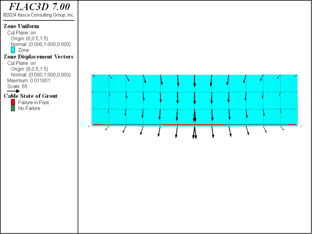
Figure 4: Final grout slip state (reduced grout cohesive strength).
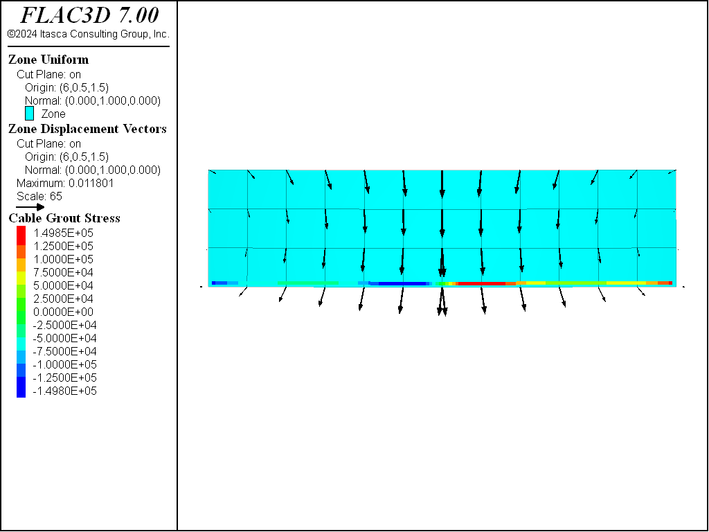
Figure 5: Final grout stress distribution (reduced grout cohesive strength).
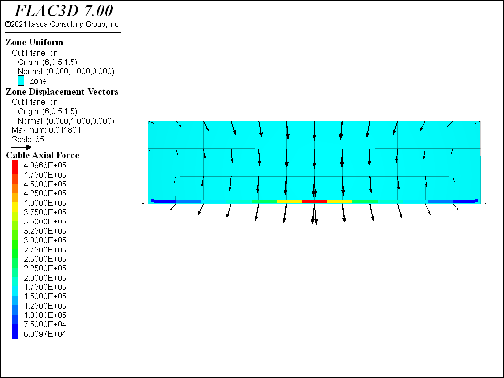
Figure 6: Final axial force distribution in cable (reduced grout cohesive strength).
Data File
ReinforcedBeam.dat
model new
model title "Cable-reinforced beam"
; Create beam (composed of zones)
zone create brick size 12 1 3
zone face skin ; Label model boundaries
; Create interface betweenthe two
zone interface create by-face separate range position-x 6.0
zone interface node property stiffness-normal 1e10 stiffness-shear 1e10 ...
                             friction 0
zone interface tolerance-contact 1e-2
; Assign constitutive model and properties
zone cmodel assign elastic
zone property bulk 1e9 shear .3e9
zone initialize density 2400
; Boundary conditions - pin on right and left lower corners
zone gridpoint fix velocity-z 0 range position-z 0 position-x 0
zone gridpoint fix velocity-z 0 range position-z 0 position-x 12
; Setup model
model gravity 10
model large-strain on
model save 'Start'
; Run problem with no cable present
zone mechanical damping combined
model cycle 3000
model save 'NoCable'
; Now rerun problem with a cable present
model restore 'Start'
; Create Cable and set properties
struct cable create by-line (0.1, 0.5, 0.1) (11.9, 0.5, 0.1) id=1 segments=13
struct cable property cross-sectional-area=2e-3 young=200e9 ...
                      yield-tension=1e20 grout-stiffness=1e10 ...
                      grout-cohesion=1e20 ; 1e11
zone mechanical damping combined
model solve ratio-local 1e-4
model save 'Cable'
; Now allow the cable to fail
struct cable property grout-cohesion 1.5e5
model solve ratio-local 1e-4
model save 'CableFail'
| Was this helpful? ... | 3DEC © 2019, Itasca | Updated: Feb 25, 2024 |