Punch Indentation of a Bonded Material
Problem Statement
Note
To view this project, use the menu command . Choose “Example Applications/PunchIndentation” and select “PunchIndentation.prj” to load. The main data files used are shown at the end of this example. The remaining data files can be found in the project.
This example demonstrates the indentation response of a bonded-particle model (BPM) when compressed by a rounded punch. A model of this nature could be investigated using PFC with: 1) a relatively large assembly of PFC balls to ensure a realistic response of the material away from the site of the indentation and 2) PFC walls representing the body of the punch. Such an approach would be rather computationally expensive due to the number of balls required outside of the punch indentation region. In addition, punch stresses/deformation could not be assessed in PFC as walls act only as rigid boundaries.
Figure 1 shows the model geometry. A region of zones are nulled and a BPM is created inside this region. Though the BPM region is small and the balls are rather large, this example effectively demonstrates the mechanics of coupling PFC and FLAC3D models. As described in detail in the Wall-Zone Coupling Scheme section, PFC walls are slaved to surface zones. Figure 2 shows the PFC walls and the model domain in which all PFC model components exist. Contacts exist between PFC balls and wall facets; the contact forces and moments at each ball-facet contact are used to determine an equivalent force system to apply to the corresponding zone gridpoints.
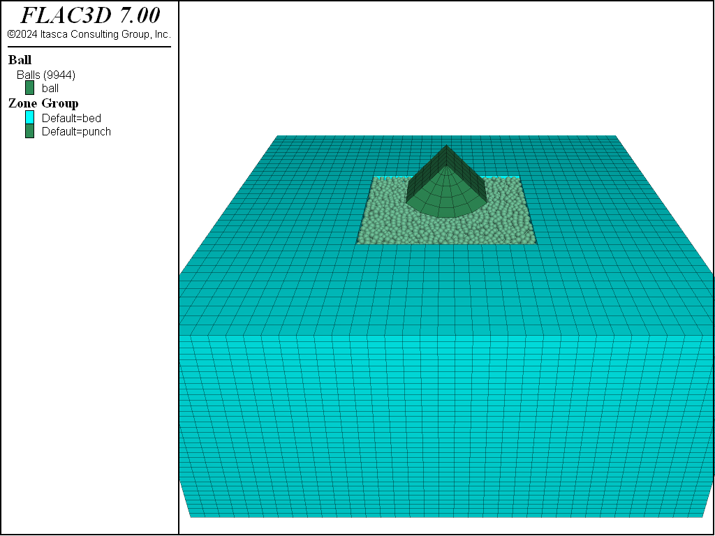
Figure 1: Geometry of PFC balls and FLAC3D zones once the BPM has been created in the zone cavity.

Figure 2: PFC walls created with the wall-zone create command.
Coupled PFC-FLAC3D Model
Prior to creating a coupled PFC-FLAC3D model, one must load the PFC modules. These are the DLLs that contain the code responsible for instantiating all PFC related model components. In addition, a set of modules exist to couple PFC walls with FLAC3D zones and shell-based structural elements. By default these modules are not loaded when the FLAC3D application is opened. One may either load these modules via the menu item or with the following commands:
program load module 'contact'
program load module 'pfc'
program load guimodule 'pfc'
program load module 'pfcthermal'
program load guimodule 'pfcthermal'
program load module 'ccfd'
program load guimodule 'ccfd'
program load module 'wallsel'
program load module 'wallzone'
Once a project has been saved with any additional modules loaded, these modules will be loaded whenever the project is opened once again. Note that the additional modules remain loaded until the FLAC3D application is closed.
PFC balls are created within the region of nulled FLAC3D zones. In order to create the same initial
cloud of balls each time the data files are run, the model random command is used to initialize
the random seed to a specified value. Changing the random seed will result in a different realization of
balls, though statistically, the realizations will be the same. Unlike zones and structural elements,
all PFC model components (i.e., balls, clumps, walls and contacts) can only exist within a user-specified
model domain (see the model domain command). This restriction allows for contact detection and
spatial searching to be simplified and optimized. As PFC always operates in large-strain mode, one
must explicitly activate large-strain mode for zones and structural elements (see the
model large-strain command). PFC, by default, solves the dynamic equations of motion using the
real inertia properties of balls and clumps. In this model, we desire to operate with timestep scaling
in PFC (see the model mechanical command), an approach which is similar to the default FLAC3D
behavior.
With these preliminary steps complete, we dive into creating the initial model.
;create a bed of zones for the balls to sit inside
zone create brick size 35 35 35 point 0 -4 -4 -4.5 point 1 4 -4 -4.5 ...
                                point 2 -4 4 -4.5 point 3 -4 -4 -1 group 'bed'
zone cmodel assign elastic
zone property young [materialMod] poisson 0.25
zone cmodel null ...
            range position-x -1.5 1.5 position-y -1.5 1.5 position-z -2 -1
;as the balls are packing into this region -
;fix the gridpoint motions as the balls are settling
zone gridpoint fix velocity

;wrap the bed with walls
wall-zone create name 'bed' starting-zone 30013
;create a wall over the top
wall generate name 'top' plane position 0 0 -1

;create a cloud of balls that are arbitrarily overlapping
ball distribute porosity 0.4 box -1.5 1.5 -1.5 1.5 -2 -1 radius 0.04 0.06

;set the ball density and local damping coefficient
ball attribute density 2600 damp 0.7
;set the default contact behavior -
;the deformability method sets properties of the linear portion
;of the contact model
contact cmat default model linearpbond method deformability ...
                   emod [materialMod] kratio 1.0
;allow the balls to rearrange, nulling the linear
;and angular velocities every 100 cycles
model cycle 1000 calm 100
;delete any balls that flew out of the bed
ball delete range position -1.5 -1.5 -2  1.5 1.5 -1 not
The zone create command is used to create a simple bed of zones and the region that the BPM will
occupy is nulled. Since the balls will be created with arbitrary overlap, all gridpoint velocities
are fixed while the balls rearrange. The wall-zone create command is used to wrap wall facets
around surface zone faces. As seen in Figure 2, the walls do not extend beyond the
model domain. An additional wall is created with the wall generate command to enclose the
cavity.
PFC balls and clumps can either be created without initial overlap or with arbitrary initial overlap.
In this case, the ball distribute command is used to create a cloud of balls with arbitrary
overlaps to a specified volume fraction within a parallelepiped volume. Ball attributes are then assigned
and the contact cmat command is used to specify the contact model behavior. With these steps taken
the balls can be allowed to rearrange. The calm keyword in the model cycle command is
used to periodically remove all kinetic energy from the system. Finally, all balls that have escaped
the generation region are deleted.
At this point the granular material is converted to a BPM.
;bond the balls together with the specified gap
contact method bond gap 2.0e-3
;set the parallel bond properties from the pb_deform method
contact method pb_deform emod [materialMod] kratio 1.0
;remove the linear portion of the contact properties
;and set the contact strength
;this will be a relatively weak material
contact property lin_mode 1 pb_ten 2e4 pb_coh 2e5 ...
        range contact type 'ball-ball'
;set the ball-facet contact strength to be very high
contact property lin_mode 1 pb_ten 1e100 pb_coh 1e100 ...
        range contact type 'ball-facet'
;remove the box
wall delete wall range name 'top'
;set the default behavior for new ball-ball and ball-facet contacts
contact cmat default model linear type ball-ball method deformability ...
                   emod [materialMod] kratio 1.0 property fric 0.3
contact cmat default model linear type ball-facet method deformability ...
                   emod [materialMod] kratio 1.0 property fric 0.3
;remove all velocities, fix the balls,
;cycle 2 to remove any contact forces that previously existed from
;the simple packing procedure
model calm
ball fix velocity spin
ball attribute force-contact multiply 0.0
contact property lin_force 0 0 0
model cycle 2
ball free velocity spin
Parallel bonds are installed with the contact method command. In addition, the parallel bond
properties are set with this same command. A contact method is a set of operations that operate to
perform a task on contacts, possibly modifying multiple contact properties. In this case, the
pb_deform method sets the pb_kn and pb_ks properties of the linear
parallel bond contact model. The parallel-bond strength of the ball-ball and
ball-facet contacts are assigned as well. It is important
to note that the ball-facet parallel-bond strengths are set to be very large to ensure that the
balls at the boundary remain bonded to their neighboring zones. Specifying lin_mode = 1 means
that, for this BPM, all forces are incrementally accumulated; prior to this
command, forces developed as a result of the absolute overlap at ball-ball and ball-facet contacts.
This allows one to produce a BPM quickly without internal stresses. To achieve this, the ball
velocities and spins are nulled and fixed so that no new contact forces will develop for a few cycles.
One must also set the contact force stored in the contact model to 0.
As a result, the BPM is in equilibrium with no internal stresses.
At this point in the modeling process, a stress-free BPM has been created within a cavity in a larger FLAC3D model. Some balls are bonded to the wall facets corresponding to the free zone faces. The forces/moment produced at these contacts are automatically conveyed to the associated zone gridpoints, allowing for the BPM and continuum models to naturally interact.
Results and Discussion
Once cycling commences, the balls begin to displace in response to the pressure applied by the punch. The punch is indented a specified distance and then the model is solved to a specified average ratio. Figure 3 and Figure 4 show the surface and cross-sectional displacements of the balls and zones, respectively. Notice the continuity of displacements between the BPM and continuum regions. In addition, the displacement field is symmetric as the BPM is acting similar to a continuum due to the fact that few bonds have broken. Figure 5 shows the locations of the few bonds that have broken to this point in the simulation.
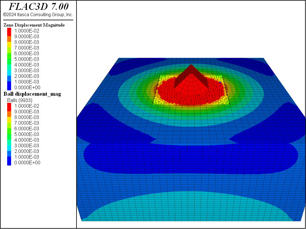
Figure 3: Surface displacements of balls and zones prior to massive failure of the BPM.
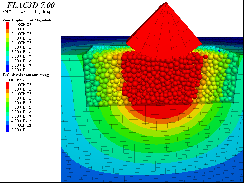
Figure 4: Cross section of displacements of balls and zones prior to massive failure of the BPM.
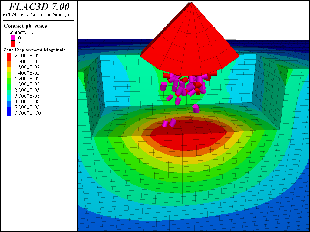
Figure 5: Broken bonds prior to massive failure of the BPM.
Subsequently the punch is depressed an additional distance into the BPM. Figure 6 and Figure 7 show the surface and cross-sectional displacements after additional motion of the punch. As compared with the displacements shown above, continued punch penetration results in significantly less displacement away from the punch. Figure 8 shows the locations of the bonds that have broken with the additional punch indentation. At this point the bulk BPM has failed with localized bond breakages. As a result, the balls rearrange and the displacements diminish significantly away from the indentation site.
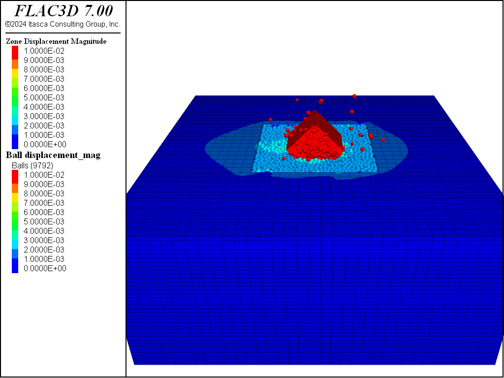
Figure 6: Surface displacements of balls and zones after massive failure of the BPM.
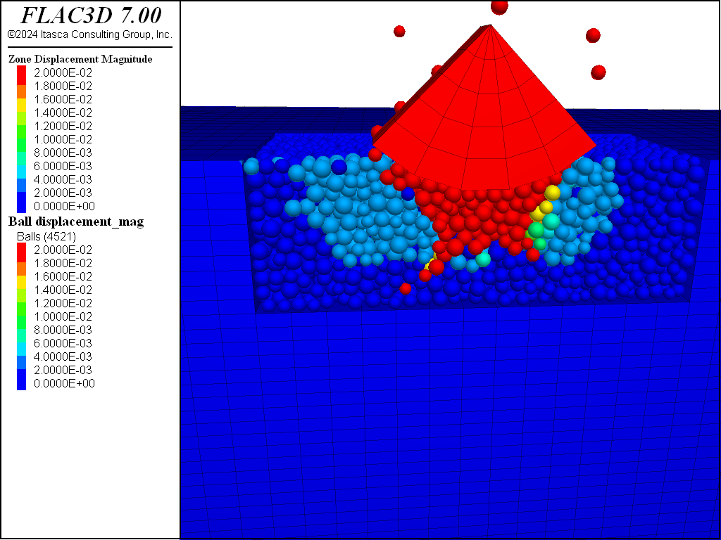
Figure 7: Cross section of displacements of balls and zones after massive failure of the BPM.

Figure 8: Broken bonds after massive failure of the BPM.
Not only do the displacements change signficantly after failure, the stresses in the punch are significantly reduced. Figure 9 and Figure 10 show the measure stress before and after bulk failure, respectively. The BPM is significantly less able to resist indentation at this point.
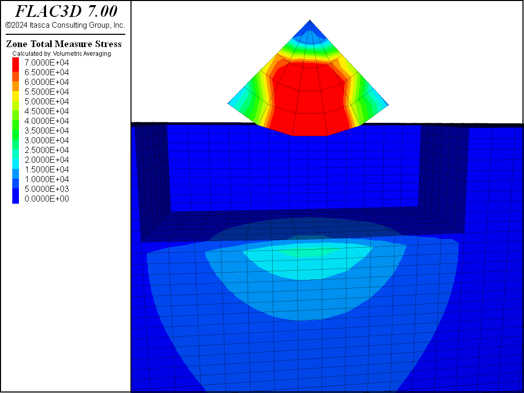
Figure 9: Total measure stress before massive failure of the BPM.
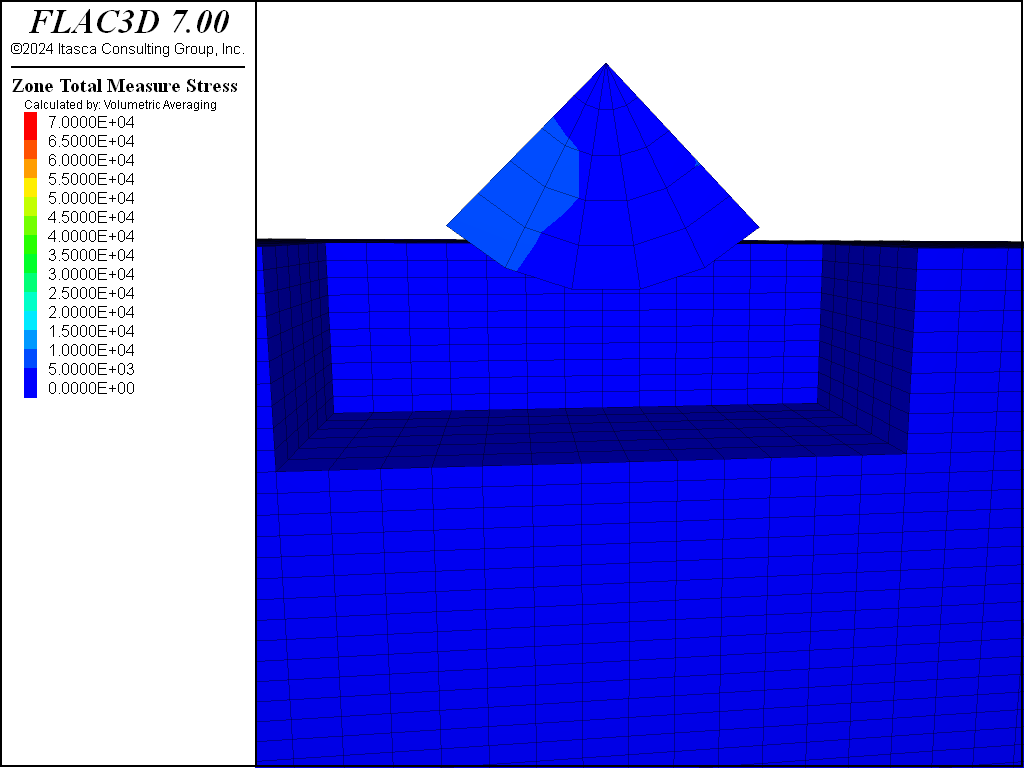
Figure 10: Total measure stress after massive failure of the BPM.
Data Files
PunchIndentation.dat
;-------------------------------------------------------------------
;                Punch Indentation of a Bonded
;                Material
;-------------------------------------------------------------------
model new
model title 'Punch Indentation of a Bonded Material'
;make repeatable by setting the random number seed
model random 10001
;set the model domain for PFC balls and walls
model domain extent -2 2 -2 2 -2.5 0 condition destroy
;largestrain mode must always be on for coupled simulations
model large-strain on
;apply timestep scaling so the PFC timestep will be 1
model mechanical timestep scale

;define the effective modulus of the DEM material -
; use this as the Young's modulus of the bed of zones as well
[materialMod = 1.0e6]
;define the Young's modulus of the zones comprising the punch
[punchYoung = 1.0e7]

;create a bed of zones for the balls to sit inside
zone create brick size 35 35 35 point 0 -4 -4 -4.5 point 1 4 -4 -4.5 ...
                                point 2 -4 4 -4.5 point 3 -4 -4 -1 group 'bed'
zone cmodel assign elastic
zone property young [materialMod] poisson 0.25
zone cmodel null ...
            range position-x -1.5 1.5 position-y -1.5 1.5 position-z -2 -1
;as the balls are packing into this region -
;fix the gridpoint motions as the balls are settling
zone gridpoint fix velocity

;wrap the bed with walls
wall-zone create name 'bed' starting-zone 30013
;create a wall over the top
wall generate name 'top' plane position 0 0 -1

;create a cloud of balls that are arbitrarily overlapping
ball distribute porosity 0.4 box -1.5 1.5 -1.5 1.5 -2 -1 radius 0.04 0.06

;set the ball density and local damping coefficient
ball attribute density 2600 damp 0.7
;set the default contact behavior -
;the deformability method sets properties of the linear portion
;of the contact model
contact cmat default model linearpbond method deformability ...
                   emod [materialMod] kratio 1.0
;allow the balls to rearrange, nulling the linear
;and angular velocities every 100 cycles
model cycle 1000 calm 100
;delete any balls that flew out of the bed
ball delete range position -1.5 -1.5 -2  1.5 1.5 -1 not

;bond the balls together with the specified gap
contact method bond gap 2.0e-3
;set the parallel bond properties from the pb_deform method
contact method pb_deform emod [materialMod] kratio 1.0
;remove the linear portion of the contact properties
;and set the contact strength
;this will be a relatively weak material
contact property lin_mode 1 pb_ten 2e4 pb_coh 2e5 ...
        range contact type 'ball-ball'
;set the ball-facet contact strength to be very high
contact property lin_mode 1 pb_ten 1e100 pb_coh 1e100 ...
        range contact type 'ball-facet'
;remove the box
wall delete wall range name 'top'
;set the default behavior for new ball-ball and ball-facet contacts
contact cmat default model linear type ball-ball method deformability ...
                   emod [materialMod] kratio 1.0 property fric 0.3
contact cmat default model linear type ball-facet method deformability ...
                   emod [materialMod] kratio 1.0 property fric 0.3
;remove all velocities, fix the balls,
;cycle 2 to remove any contact forces that previously existed from
;the simple packing procedure
model calm
ball fix velocity spin
ball attribute force-contact multiply 0.0
contact property lin_force 0 0 0
model cycle 2
ball free velocity spin
;fix the z- velocity of zones at the bottom of the model
zone gridpoint free velocity
zone gridpoint fix velocity-z range position-z -5 -4.4
;reset the ball displacement
ball attribute displacement multiply 0.0
model save 'withoutPunch'

;create the rounded punch and assign properties to it
zone create cylinder point 0 0 -0.5 0 ...
                  point 1 [-math.sqrt(2.0)/2.0] -0.5 [-math.sqrt(2.0)/2.0] ...
                  point 2 0 0.5 0 ...
                  point 3 [math.sqrt(2.0)/2.0] -0.5 [-math.sqrt(2.0)/2.0] ...
                  size 5 5 5 group 'punch'
zone cmodel assign elastic range group 'punch'
zone property young [punchYoung] poisson 0.25 range group 'punch'
;wrap the punch with walls
wall-zone create range group 'punch'
;assign a group the gridpoints on the top of the punch and fix the z- velocity
zone gridpoint group "fixed" range position-z -0.4 1
zone gridpoint fix velocity-z -.0001 range group "fixed"
model save 'withPunch'

;push the punch into the balls with just minimal failure of the material
model cycle 1000
zone gridpoint fix velocity-z 0.0 range group "fixed"
;solve to an equilibrium state to show the current displacements
model solve ratio-average 1.0e-4
model save 'beforeFailure'

;push the punch in and watch the zone displacement
;diminish after the onset of failure
zone gridpoint fix velocity-z -.0001 range group "fixed"
model cycle 1000
zone gridpoint fix velocity-z 0.0 range group "fixed"
;failure will continue and the granular specimen will rearrange,
;reducing the displacements
model solve ratio-average 1.0e-3
model save 'afterFailure'
| Was this helpful? ... | 3DEC © 2019, Itasca | Updated: Feb 25, 2024 |