Sliding and Toppling Blocks
Problem Statement
Note
To view this project in 3DEC, use the menu command . Choose “3DEC/ VerificationProblems/ Sliding_Block” and select “Sliding_Block.prj” to load. The main data files used are shown at the end of this example. All data files are found in the project.
The stability of a single block of different dimensions and properties on a slope of different angles is analyzed and compared to an analytical solution.
Analytical Solution
The stability of blocks on a slope with different geometries and friction angles are shown by Wyllie and Mah (2004). This is summarized in Figure 1,
where:
\(\phi\) = the friction angle;
\(\psi_p\) = the slope angle.
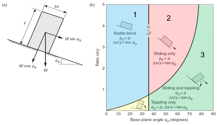
Figure 1: Identification of sliding and toppling blocks: (a) geometry of block on inclined plane; (b) conditions for sliding and toppling of block on an inclined plane. From Wyllie and Mah (2004).
3DEC Models
Four different 3DEC models are run to test the different stability regimes. All models have the following properties:
density: \(\rho\) = 2000 kg/m3
joint shear and normal stiffness: \(K_n\) = \(K_s\) = 10 MPa/m
gravity acceleration: \(g\) = 10 m/sec2
block width: \(\Delta x\) = 10 m
The block height, joint friction angle and slope angle are varied for each test.
Stable
For the stable case, the following parameters are used:
block height: \(y\) = 10 m
friction angle: \(\phi\) = 40.1 degrees
slope angle: \(\psi_p\) = 40 degrees
The block displacement after 700 steps is shown in Figure 1. The block is not moving, as expected.
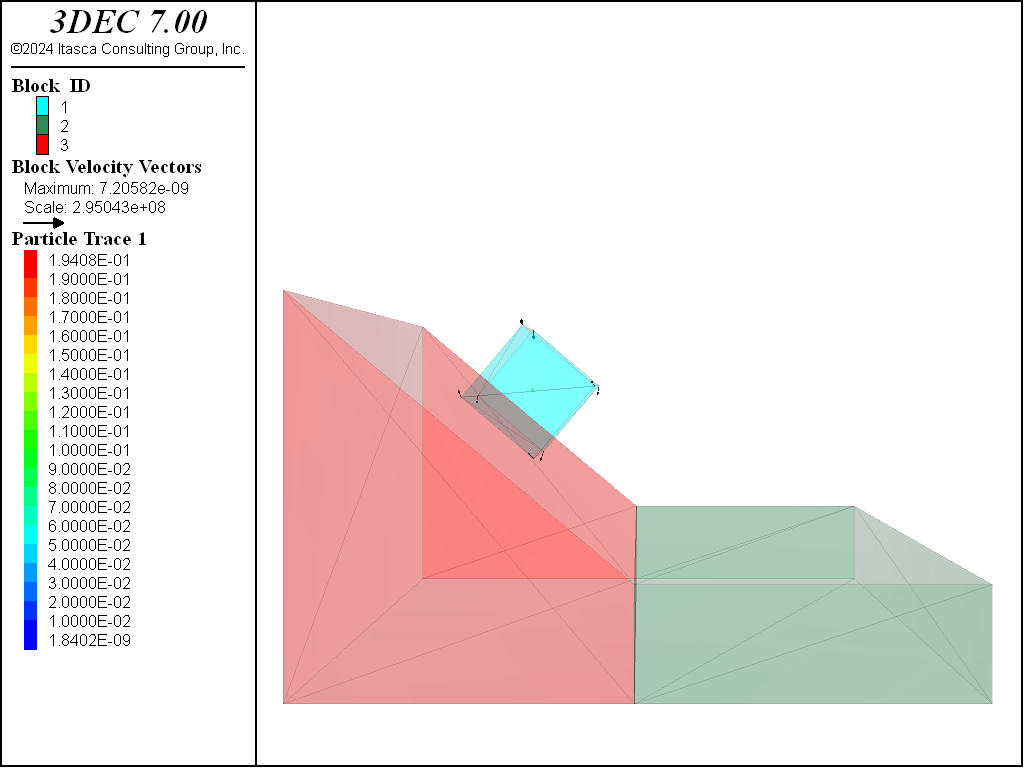
Figure 2: Block geometry and displacements in the stable model.
Sliding
To test the sliding condition, the following parameters were used:
block height: \(y\) = 5 m
friction angle: \(\phi\) = 20 degrees
slope angle: \(\psi_p\) = 40 degrees
Figure 2 shows the situation after 500 steps. The block arrows show gridpoint velocities and indicate that the block is still moving down the slope. The colored line shows the path of the block centroid from blue (early time) to red (later time). The block is sliding down the slope as expected.
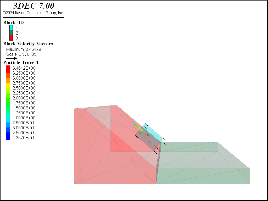
Figure 3: Block geometry, displacements and trace of block movement in the sliding model.
Toppling
The toppling case is simulated with the following:
block height: \(y\) = 25 m
friction angle: \(\phi\) = 40 degrees
slope angle: \(\psi_p\) = 40 degrees
The results are shown in Figure 3. As in Figure 2, the bloack arrows show the velocities and the colored line shows the trace of the block centroid. In this case it is clear that the block is toppling.
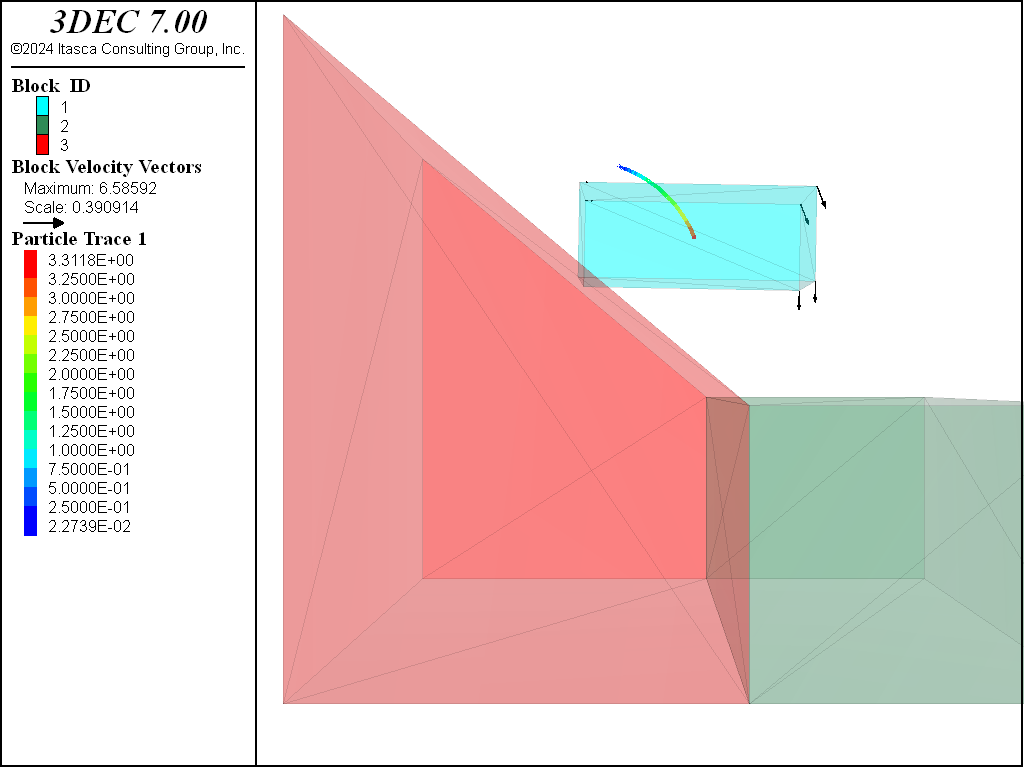
Figure 4: Block geometry, displacements and trace of block movement in the toppling model.
Toppling and Sliding
The final test is to simulate a combination of toppling and sliding. The following parameters are used:
block height: \(y\) = 20 m
friction angle: \(\phi\) = 30 degrees
slope angle: \(\psi_p\) = 40 degrees
Figure 4 shows the results. When comared to Figure 2 and Figure 3, it can be seen that the block is indeed sliding and toppling.
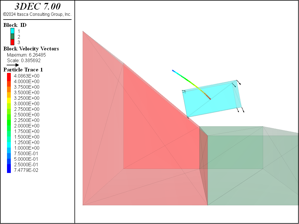
Figure 5: Block geometry, displacements and trace of block movement in the sliding and toppling model.
Reference
Wyllie, D. C., C.W. Mah. “Rock Slope Engineering”, 4th edition, Spon Press (2004).
Data Files
stable.dat
;STABLE
model new
program call 'build_blocks.dat'
[factor = 1]    ; ratio of width to height
[fi_p = 40]     ; slope angle
[make_blocks]

[fi = 40.1]      ; friction angle

; properties in MPa
block property density 2e-3
block contact material-table default property stiffness-normal 10 ...
  stiffness-shear 10 friction [fi]
model gravity 0 0 -10
model large-strain on

; take displacement history of point on the top
block history displacement position [f1_x2] [f1_y] [f1_z2]

; trace block centroid
block trace id 1
model cycle 700

model save 'stable'
sliding.dat
;SLIDING
model new
program call 'build_blocks.dat'
[factor = 2]    ; ratio of width to height
[fi_p = 40]     ; slope angle
[make_blocks]

[fi = 20]      ; friction angle

; properties in MPa
block property density 2e-3
block contact material-table default property stiffness-normal 10 ...
  stiffness-shear 10 friction [fi]
model gravity 0 0 -10
model large-strain on

; take displacement history of point on the top
block history displacement position [f1_x2] [f1_y] [f1_z2]

; trace block centroid
block trace id 1
model cycle 500

model save 'sliding'
toppling.dat
;TOPPLING
model new
program call 'build_blocks.dat'
[factor = 0.4]    ; ratio of width to height
[fi_p = 40]     ; slope angle
[make_blocks]

[fi = 50]      ; friction angle

; properties in MPa
block property density 2e-3
block contact material-table default property stiffness-normal 10 ...
  stiffness-shear 10 friction [fi]
model gravity 0 0 -10
model large-strain on

; take displacement history of point on the top
block history displacement position [f1_x2] [f1_y] [f1_z2]

; trace block centroid
block trace id 1
model cycle 800

model save 'toppling'
sliding_toppling.dat
;SLIDING and TOPPLING
model new
program call 'build_blocks.dat'
[factor = 0.5]    ; ratio of width to height
[fi_p = 40]     ; slope angle
[make_blocks]

[fi = 30]      ; friction angle

; properties in MPa
block property density 2e-3
block contact material-table default property stiffness-normal 10 ...
  stiffness-shear 10 friction [fi]
model gravity 0 0 -10
model large-strain on

; take displacement history of point on the top
block history displacement position [f1_x2] [f1_y] [f1_z2]

; trace block centroid
block trace id 1
model cycle 700

model save 'sliding_toppling'
build_blocks.dat
; functions to build slope and falling block
fish auto-create off
fish define make_blocks
;=============================
  global deltax = 10.0 ; block width
  global factor        ; ratio of height to width
  global fi_p          ; joint inclination
;==============================
  global z_=deltax/factor ;slope height
  global alfa_deg=(90-fi_p)

  ; angles in radians
  local alfa_rad=(90-fi_p)*math.degrad
  local fi_p_rad = fi_p*math.degrad

  ; slope block coordinates
  global xlow=0
  global xup=3*deltax*math.cos(fi_p_rad)+z_*math.cos(alfa_rad)
  global ylow=0
  global yup=5*deltax
  global zlow=0
  global zup=z_ + 2*deltax*math.sin(fi_p_rad) + z_*math.sin(alfa_rad)+0.5*z_
  global xupp=xup+3*deltax

  ; falling block coordinates
  local height = z_
  local bot_cenx = 0.5*(xlow+xup)
  local bot_cenz = z_+(xup-bot_cenx)*math.tan(fi_p_rad)

  global f1_x1 = bot_cenx - 0.5*deltax*math.cos(fi_p_rad)
  global f1_z1 = bot_cenz + 0.5*deltax*math.sin(fi_p_rad)
  global f1_x4 = bot_cenx + 0.5*deltax*math.cos(fi_p_rad)
  global f1_z4 = bot_cenz - 0.5*deltax*math.sin(fi_p_rad)
  global f1_x2 = f1_x1 + height*math.sin(fi_p_rad)
  global f1_z2 = f1_z1 + height*math.cos(fi_p_rad)
  global f1_x3 = f1_x4 + height*math.sin(fi_p_rad)
  global f1_z3 = f1_z4 + height*math.cos(fi_p_rad)

  global f1_y = 0.5*(ylow+yup) - 0.5*deltax
  global f2_y = f1_y + deltax

  command
    ; make bricks
    block create brick [xlow] [xup] [ylow] [yup] [zlow] [zup]
    block create brick [xup] [xupp] [ylow] [yup] [zlow] [z_] group '40'
    block hide range group '40'

    ; cut slope
    block cut joint-set dip [fi_p] d-d 90 ori [xup] [ylow] [z_] jointset-id 1
    block delete range plane dip [fi_p] d-d 90 ori [xup] [ylow] [z_] above
    block hide off

    block fix

    ; make falling block
    block create prism face-1 [f1_x1],[f1_y],[f1_z1] ...
                              [f1_x2],[f1_y],[f1_z2] ...
                              [f1_x3],[f1_y],[f1_z3] ...
                              [f1_x4],[f1_y],[f1_z4] ...
                       face-2 [f1_x1],[f2_y],[f1_z1] ...
                              [f1_x2],[f2_y],[f1_z2] ...
                              [f1_x3],[f2_y],[f1_z3] ...
                              [f1_x4],[f2_y],[f1_z4]
  end_command
end

fish auto-create on
| Was this helpful? ... | FLAC3D © 2019, Itasca | Updated: Feb 25, 2024 |