Plot Item Cutting Tool
The cutting tool is used to apply a cutting object (a plane, wedge, or octant) to its parent plot item.
Show a cutting tool (make the plane/wedge/octant visible in the plot) by selecting it in the “Plot Item List.” It is removed from view when a different object is selected on the “Plot Item List.”
Activate a cutting tool (turn on its cutting action in the plot) or de-activate by toggling its  button.
Note showing and activating are independent of one another.
A cutting tool may be copied/pasted onto another plot item. This operation can be performed across plots.
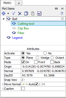
When a cutting tool is selected in the “Plot Items” list, the lower Attributes section of the control set (see adjacent image) will show its properties. These may be adjusted in the Attributes section of the control set, or they may be adjusted interactively by operating on the cutting tool within the plot.
Cutting Tool Attributes
Activate: This is equivalent to using its on/off toggle button ( ). Selecting “Yes” will cause the tool to cut the plot item; selecting “No” will leave the plot item unaffected. In either case, the cutting tool is visible while it remains selected in the upper portion of the control set. This means that while “No” is selected, the cutting tool can be manipulated, but its cutting effect will not be shown.
Type: Specify which of three shapes (“Plane,” “Wedge,” or “Octant”) the cutting tool should assume. Note that there will be one set of positioning attributes (“Origin,” “Normal,” and “Dip/DD”) when “Plane” is selected. There will be two or three (one for each plane) if “Wedge” or “Octant” (respectively) are selected.
Sync To: Specify a name for the cutting tool of the current type. Cutting tools of plot items are synced if they share the same name and type: changes made on one cutting tool will be reflected on all synced tools. Set the field blank to prevent cutting tool syncing for the parent plot item. Cutting tools of each type are initially named “Default” when the plot item is added to the plot.
Mode: Specify how the tool will cut. If “On” is selected, only the slice of the the plot item that coincides with the plane is rendered. If “Back” is selected, the plot item is cut at the position of the plane, and any portion of the plot item that is “behind” the plane is fully rendered. If “Front” is selected, the plot item is cut at the position of the plane, and any portion of the plot item that is in front of the plane is fully rendered. These switches may be combined.
Origin: Set the origin of the plane.
Normal: Set the position of the coordinate that, with the origin, forms the plane normal.
Dip/DD: Set the dip and dip direction, respectively, of the plane. This setting may be used as an alternative to the “Origin” and “Normal” settings for positioning the cutting tool. Changes in either are bidirectional.
Snap View: Press the button to “snap” the view to an orientation perpendicular on the plane (straight down) so that the screen represents the plane surface. Pressing the button again will do the same thing but from the opposite direction.
Move Normal: Allow the cutting tool to be moved incrementally, perpendicular to its normal in one direction (left arrow) or the other (right arrow). The increment by which it is moved may be manually specified if the “Auto” box is unchecked.
Working on a Cutting Tool in the Plot
A cutting tool comprises one (“Plane”), two (“Wedge”), or three (“Octant”) planes that may be positioned and oriented interactively on the screen.
Free Positioning: Move the mouse toward the origin point, which is shown as a square (  ) on the cutting tool.
When the mouse has gotten close enough to position the cutting tool, the cursor will change to an open hand (
) on the cutting tool.
When the mouse has gotten close enough to position the cutting tool, the cursor will change to an open hand (  ).
Click and drag to move the cutting tool.
).
Click and drag to move the cutting tool.
Positioning Along Normal: This works the same way as Free Positioning, but hold the Ctrl key to constrain
the positioning of the origin to locations along the plane normal. This operation is also available using the Page Up
and Page Down keys.
3D Rotate: When the mouse cursor is not close enough to the origin to position the origin, the cursor will display
as a finger pointer (  ). Click and drag the plane of interest to 3D-rotate to the desired orientation.
2D Rotate: This works the same way as 3D rotate, but hold the Ctrl key to rotate the cutting tool around
the screen normal.
Change Wedge Angle: Position the mouse over the red normal indicator of a wedge face. When the hand cursor appears, click and drag to change the wedge angle. (This is only available when the Type attribute is set to “Wedge.”)
CS: figure of clipbox needs to be updated to include sync field
| Was this helpful? ... | FLAC3D © 2019, Itasca | Updated: Feb 25, 2024 |