Views
An extrusion set is created in a two-step process: 1) define the 2D shape to be extruded, and 2) delineate the orientation and extent of the extrusion. The Extrusion pane provides two distinct views to performg these steps: the construction view, and the extrusion view.
Construction View
The construction view is accessed using the construction view button ( ) on the toolbar. This view is used to draw a 2D shape which is to be meshed and extruded. This shape is rendered using nodes and edges arranged into closed polygons. Simply-connected 3- or 4-sided polygons (referred as regular blocks) can be meshed with structured or unstructured mesh; all other types of polygons (referred as irregular blocks) can only be meshed with unstructured mesh. The resolution of the mesh in each block is defined by the discretization of the bounding edges into segments (or zones).
These operations — briefly delineated here — are treated in complete detail in the section Operations in the Construction View.
) on the toolbar. This view is used to draw a 2D shape which is to be meshed and extruded. This shape is rendered using nodes and edges arranged into closed polygons. Simply-connected 3- or 4-sided polygons (referred as regular blocks) can be meshed with structured or unstructured mesh; all other types of polygons (referred as irregular blocks) can only be meshed with unstructured mesh. The resolution of the mesh in each block is defined by the discretization of the bounding edges into segments (or zones).
These operations — briefly delineated here — are treated in complete detail in the section Operations in the Construction View.
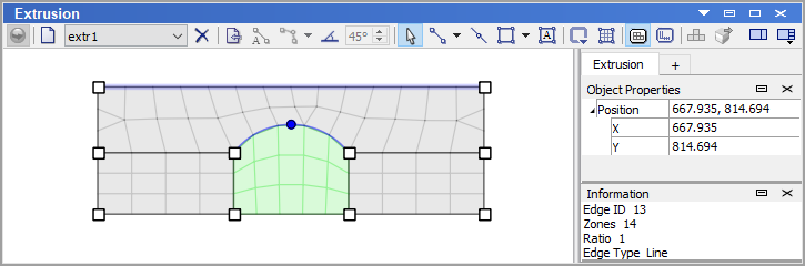
Figure 1: The construction view of the Extrusion pane
Extrusion View
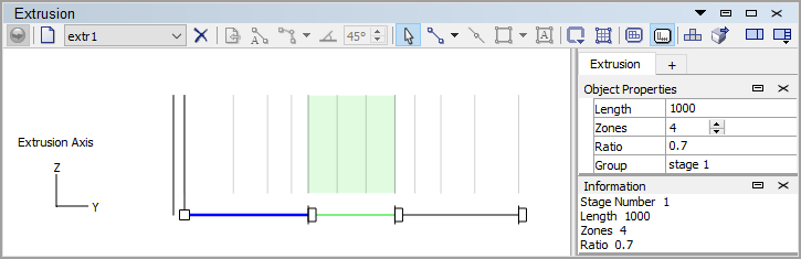
The extrusion view is accessed by pressing the extrusion view button ( ) on the toolbar. This view is used to define the extent of the extrusion, its zoning, direction and orientation. Once these aspects have been defined and operations in the construction view are complete as well, the extrusion set may be turned into zones by pressing the extrude button (
 ) on the toolbar. If the extrusion set (construction view) contains blocks with structured mesh only, user can send the extrusion to the Building Blocks pane, using the “Create building blocks…” tool button (
 ), to modify the model in 3 dimensions before creating zones.
The operations briefly delineated here are described fully in the section Operations in the Extrusion View.
), to modify the model in 3 dimensions before creating zones.
The operations briefly delineated here are described fully in the section Operations in the Extrusion View.
| Was this helpful? ... | FLAC3D © 2019, Itasca | Updated: Feb 25, 2024 |