Influence of Slope Curvature on Stability
Problem Statement
Note
The project file for this example is available to be viewed/run in FLAC3D.[1] The project’s main data file is shown at the end of this example.
Actual slopes are not infinitely long and straight: usually, they are curved in both plan and elevation. The effect of slope curvature can really only be analyzed with a three-dimensional model.
Hoek and Bray (1981) observed that the lateral restraint provided by material on either side of a potential slope failure will increase as the slope becomes more concave. They recommend that when the radius of curvature of the slope is less than the height of the slope, the allowed slope angle can be 10° steeper than the angle suggested by conventional two-dimensional stability analyses. Further, for radii of curvature greater than twice the slope height, the maximum slope angle given by a two-dimensional analysis should be used.
The model shown in Figure 1 represents a quarter-section of an open pit. The height of the slope is 25 m, and the slope angle is 2 vertical to 1 horizontal (approximately 63°). It is expected that plane-strain conditions will prevail along the plane y = -30 (see Figure 2), while axisymmetric conditions will be predominant at the plane x = 0 (see Figure 3).
The free water surface imposed in this problem is shown in Figure 4. This surface intersects the top of the model 50 m behind the toe of the slope, and there is seepage on the bottom half of the slope face. This water table, under steady-state conditions, will lead to the pore-pressure distribution shown in Figure 5.
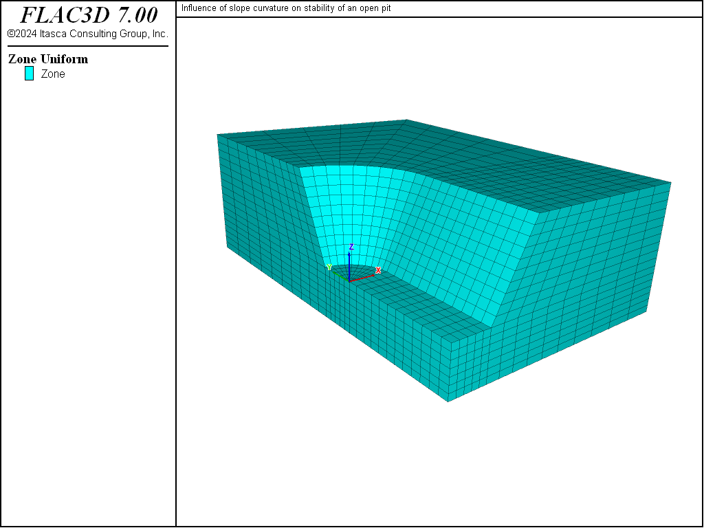
Figure 1: “Bathtub” model to evaluate slope curvature.
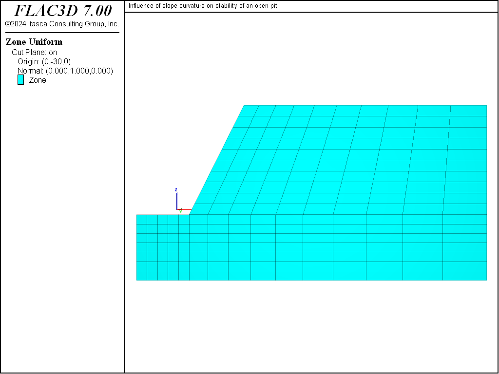
Figure 2: Vertical plane through model at y = -30.
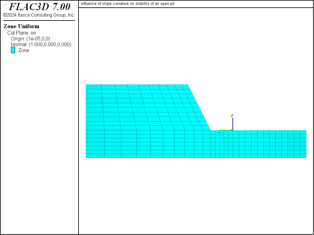
Figure 3: Vertical plane through model at x = 0.
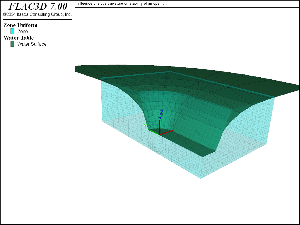
Figure 4: Free water surface.
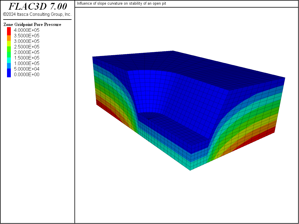
Figure 5: Pore-pressure contours.
The strength parameters chosen for this model are selected for comparison of FLAC3D results to circular failure charts published by Hoek and Bray (1981). Figure 6 shows which chart to use as a function of the groundwater flow conditions. In our case, the chart used is number 4. For example, if we assume a friction angle of 45° (tanϕ = 1) and a factor of safety F = 1, then we can draw a horizontal line in chart number 4 (see Figure 7) until we intersect the slope angle of 63°. If we draw a vertical line, we obtain a value of 0.06 for c/γ‘‘H‘‘F. For a specific weight, γ, of 25,000 N/m3 and a height, H, of 25 m, we obtain a cohesion of 37.5 kPa.
For our analysis, we select a cohesion value of 100 kPa in order to start with a stable slope. The value for c/γ‘‘Htanϕ is then 0.16 and, using Figure 7, the value for c/γ‘‘H‘‘F is 0.1 and F is 1.61.
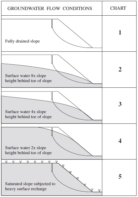
Figure 6: Chart number as a function of groundwater flow conditions (adapted from Hoek and Bray 1981).
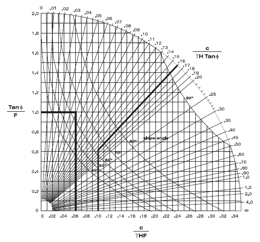
Figure 7: Circular failure chart number 4 (Hoek and Bray 1981).
Modeling Procedure
The FLAC3D model shown in Figure 1 was created interactively using the Building Blocks pane. The State Record pane was used to convert the result to a data file called “geometry.dat”. The contents of the Building Blocks pane can be be viewed after restoring any of the resulting data files.
The free water surface is imported from a DXF file. In this case, the DXF file is created via FISH in the file “create-water.dat”, but it could just as easily have come from any source.
The model is assigned a Mohr-Coulomb material model and several properties:
| bulk modulus | 200 MPa |
| shear modulus | 100 MPa |
| friction angle | 45° |
| cohesion | 100 kPa |
| tension limit | 100 kPa |
The mass density of the dry material is 2500 kg/m3, the mass density of the saturated material is 2600 kg/m3, and gravity is specified at 10 m/sec2 acting in the negative z-direction. The geometry-count range element is used to assign the saturated density to zones below the water table surface. Roller boundaries are placed along the sides of the model, and the bottom of the model is pinned.
The factor of safety is calculated by the strength reduction method using the model factor-of-safety command. The convergence criteria is changed to a local-ratio of 1e-3, as this is a stricter condition than the default.
A value of 1.70 is calculated for F. This is slighly higher than the factor of safety produced by the circular failure chart, which suggests that there is a slight effect of slope curvature on the stability. The resulting failure surface is depicted by the displacement contour plot shown in Figure 8; the plot is made after restoring the file “slopefos-Unstable.f3sav”. This plot shows that a “scoop-shaped” failure surface develops along the long side of the bathtub, but the slope is stable at the end.
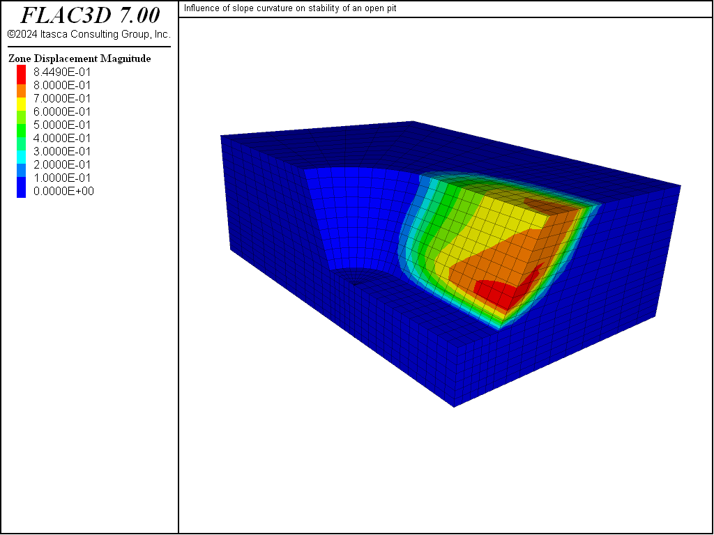
Figure 8: Displacement contours in the FLAC3D model at the failure state.
This problem was also run with the two-dimensional program FLAC in both plane-strain mode (see data file “SL-PS.DAT”) and axisymmetry mode (see data file “SL-AXI.DAT”). The model geometry was created to match that in the vertical section through the FLAC3D model (see Figure 9).
The calculation for factor of safety in the plane-strain model matches that from the circular failure chart, F = 1.61. The displacement contour and vector plot at failure shows a similar failure surface to that from FLAC3D. Compare Figure 8 to Figure 11, which plots displacement contours and vectors on a vertical plane through the FLAC3D model at y = -30.
The factor of safety calculation for the axisymmetric model produces a value for F = 2.35. This further indicates that the greater curvature produces a more stable slope.
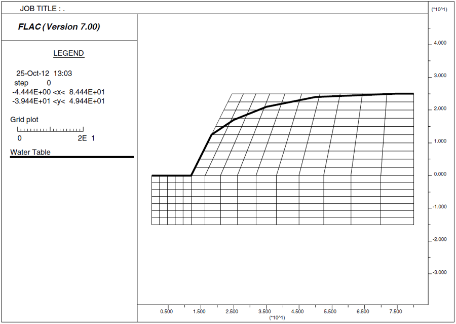
Figure 9: The FLAC model grid.
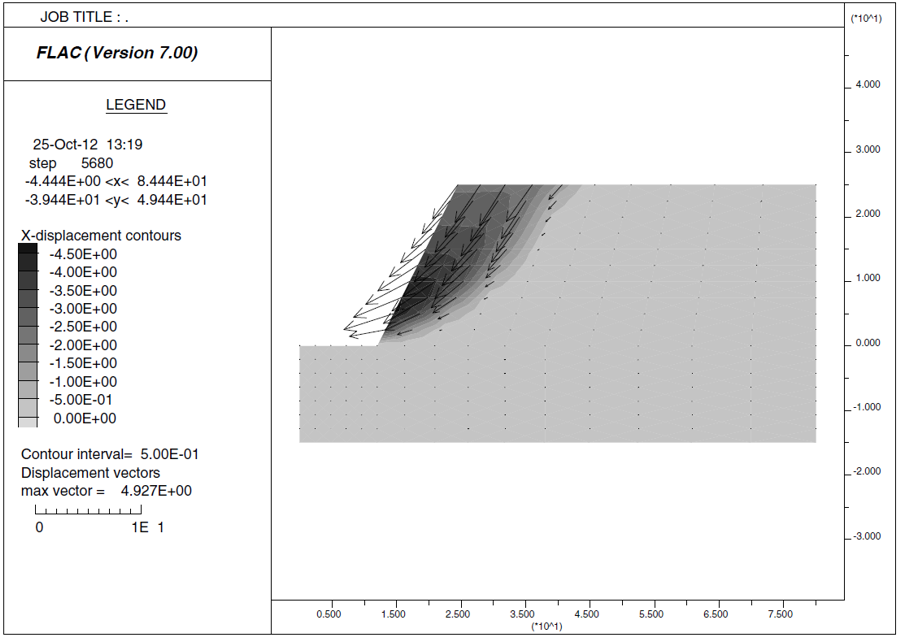
Figure 10: Displacement contours and vectors for plane-strain FLAC model.
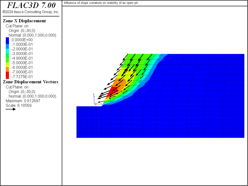
Figure 11: Displacement contours and vectors for FLAC3D model along a vertical plane at y = -30.
Reference
Hoek, E., and J. W. Bray. Rock Slope Engineering, 3rd Ed. London: The Institute of Mining and Metallurgy (1981).
Data File
SlopeCurvature.dat
;-------------------------------------------------------------
;  influence of slope curvature on stability of an open pit
;-------------------------------------------------------------
model new
model large-strain off
fish automatic-create off
model title 'Influence of slope curvature on stability of an open pit'
; Model created using Building-Blocks, data file exported from State Record
program call 'geometry' suppress
zone generate from-building-blocks set 'CurvedSlope'
; initialize gravity
model gravity 10
; Import water table from DXF file.
geometry import 'water.dxf'
zone water density 1000
zone water set 'water'
; assign Mohr Coulomb model and properties
zone cmodel assign mohr-coulomb
zone property bulk 2e8 shear 1e8 friction 45 cohesion 1e5 tension 1e5
; boundary conditions
zone gridpoint fix velocity-x range union position-x   0 position-x 80
zone gridpoint fix velocity-y range union position-y -40 position-y 80
zone gridpoint fix velocity   range position-z -15
; Initialize unsaturated density
zone initialize density 2500
; Initialize saturated density below water table
zone initialize density 2600 ...
     range geometry-space 'water' count 1 direction (0,0,1)
; initialize stresses
zone initialize-stresses total
; histories
history interval 10
model history mechanical ratio-local
zone history displacement-x position (24.5, -40,25)
zone history displacement-z position (24.5, -40,25)
zone history displacement-x position (24.5,   0,25)
zone history displacement-y position (24.5,   0,25)
zone history displacement-z position (24.5,   0,25)
zone history displacement-y position (   0,24.5,25)
zone history displacement-z position (   0,24.5,25)
; calculate fos
model factor-of-safety ratio-local 1e-3
Endnotes
| [1] | To view this project in FLAC3D, use the program menu.
⮡ FLAC |
⇐ Failure of a Slope with a Complex Surface Profile in a Mohr-Coulomb Material | Simple Slope in Hoek-Brown Material ⇒
| Was this helpful? ... | FLAC3D © 2019, Itasca | Updated: Feb 25, 2024 |