UCS Test with Fragmentation
Note
The project file for this example may be viewed/run in 3DEC.[1] The data files used are shown at the end of this example.
Problem Description
This example describes how to conduct a simple Unconfined Compressive Strength test on a bonded block model (BBM) with a square cross-section. The model simulates an assembly of bonded blocks cut by a Discrete Fracture Network. The fragments resulting from the compression test are computed and visualized.
3DEC Model
The bonded-block model is constructed by creating a 6x6x10 m block and then zoning it with tetrahedral zones with an edge length of 0.5 m. The zones are then exported as blocks. The existing model is cleared with a cmd:\(model.new\) command and the tetrahedral blocks are imported.
0.5 m is cut away from the four vertical edges. This is done because the tetrahedral zoning tends to produce aligned zones along the edge faces and can yield unrealistically high strengths due to the “crystalline” packing of blocks along the edges.
A Discrete Fracture Network (DFN) is then created with a power-law size distribution and a minimum and maximum fracture diameter of 0.5 and 10 m respectively. The DFN and an utline of the generated blocks is shown in Figure 1.
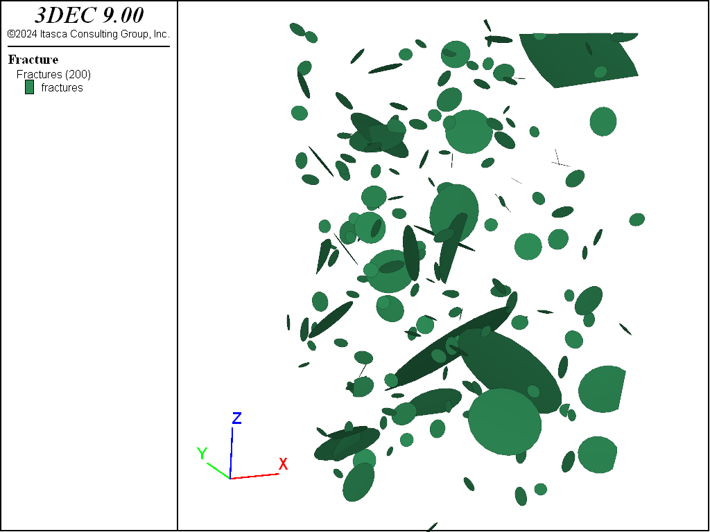
Figure 1: The DFN used to cut the model.
The model is then cut by the DFN. The resulting blocks are shown in Figure 2
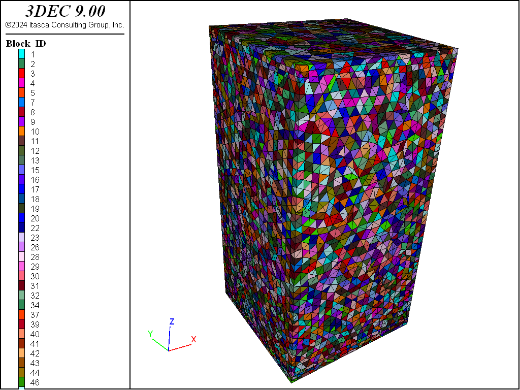
Figure 2: Blocks making up the model.
The model is then zoned and joint properties are assigned. The joints between the tetrahedral blocks are assigned a relatively high strength, while the joints inside of the DFN fractures are given a lower strength as shown in table.
|
|
|
Normal stiffness |
50 GPa/m |
50 GPa/m |
Shear stiffness |
10 GPa/m |
10 GPa/m |
Cohesion |
1 MPa |
0 |
Friction |
30^{circ} |
30^{circ} |
Tension |
0.1 MPa |
0 |
The joints with low strength that lie inside of the DFN fractures are shown in Figure 3
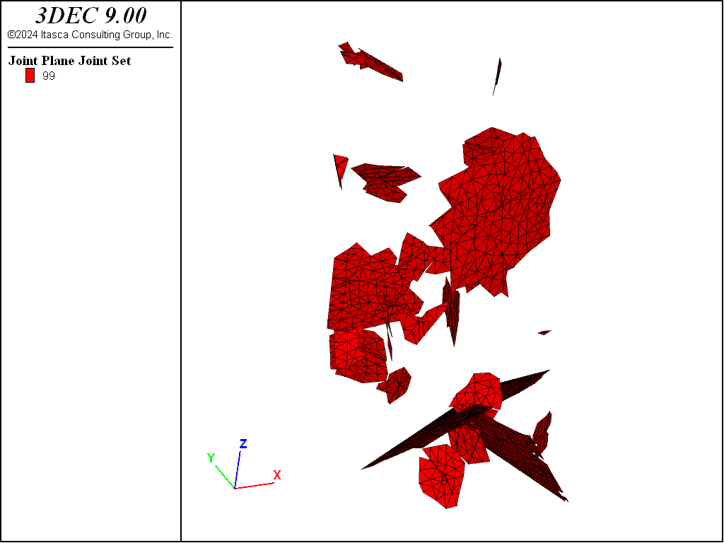
Figure 3: DFN joints in the model.
The zones are assumed to be elastic with a Young’s modulus of 1 GPa and a Poisson’s ratio of 0.25.
Loading and Monitoring
The block is loaded by applying a constant velocity of 0.1 m/s to the gridpoints on the top and bottom of the block. Axial stress is calculated by summing the vertical (z) reaction forces of all the top and bottom gridpoints and dividing by twice the cross-sectional area. The axial strain is simply the sum of displacement of the top and bottom gridpoints divided by the original length.
The model is then cycled for 10,000 steps. The model solve command is not used because the model will never reach equilibrium.
Results and Discussion
The 3DEC simulation yields a stress-strain curve as shown in Figure 4. The sample behaves in a fairly brittle manner as expected with a peak strength of 3.2 MPa.
The resulting fragments are shown in Figure 5. A fragment is defined as a collection of blocks connected together by intact bonds (joints that have not failed in tension or shear). Separate fragments are separated by joints with broken bonds. The fragments suggest an axial splitting type mechanism, which is commonly observed in UCS tests in brittle rock.
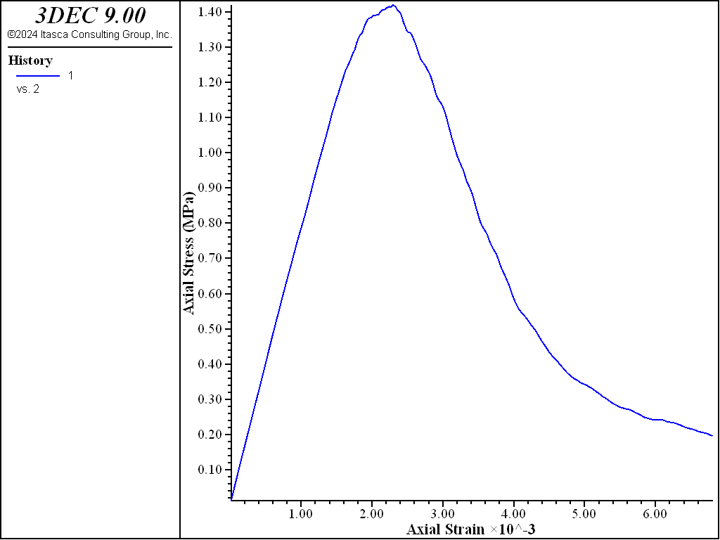
Figure 4: Axial stress versus axial strain in the UCS test.
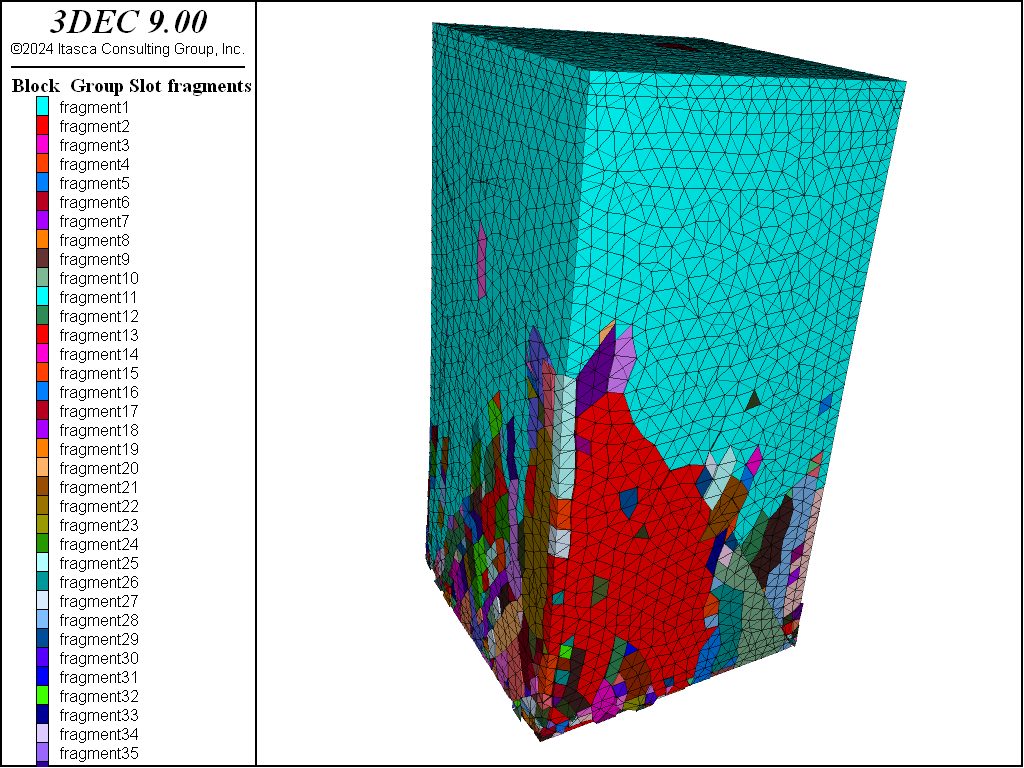
Figure 5: Fragments at the end of the UCS test.
Data Files
fragment.dat
; fname: fragment.dat
;
; Illustrate how the Fragment logic can be used
; to study the fragmentation of a Bonded Block Model.
;
;==================================================================
model new
model random 10001

; make model wider than we want so we can trim off the aligned edges
block create brick -3 3 -3 3 -5 5
block zone generate edgelength 0.5

block zone list polyhedra
;
;===================================================================

model new
model random 10001
model large-strain on
model title 'Fragmentation of a Bonded Block Model'
model domain extent -6 6 -6 6 -10 10

; add DFN
fracture template create 'dfn1' size power-law 3 size-limits 0.5 10
fracture generate template 'dfn1' dfn 'realization_1' fracture-count 200

program call 'poly'

; trim off edges
block cut joint-set dip 90 dip-direction 90 origin 2.5 0 0
block delete range position-x 2.5 3

block cut joint-set dip 90 dip-direction 90 origin -2.5 0 0
block delete range position-x -3 -2.5

block cut joint-set dip 90 dip-direction 0 origin 0 2.5 0
block delete range position-y 2.5 3

block cut joint-set dip 90 dip-direction 0 origin 0 -2.5 0
block delete range position-y -3 -2.5

; cut DFN
block cut dfn name 'realization_1' jointset-id 99

; generate zones
block zone generate edgelength 0.25

; assign contact properties
block contact jmodel assign mohr
block contact property stiffness-normal 5e10 stiffness-shear 1e10 ...
  friction 30 cohesion 1e6 tension 1e5

; Outside of DFN should be infinitely strong.
; Command not necessary in thistory case since fractures will stop
;   at tet block boundaries
;block contact property cohesion 1e12 tension 1e12 range joint-set 99

; now set realistic strength forigin fractures
block contact property cohesion 0 tension 0 range dfn-3dec 'realization_1'

block contact material-table default jmodel mohr
block contact material-table default property stiffness-normal 5e10 ...
  stiffness-shear 1e10 friction 30

; zone properties
block zone cmodel assign elastic
block zone property density 2000 young 1e9 poiss 0.25

; set up stress and strain histories
block gridpoint group 'top' range position-z 5
block gridpoint group 'bottom' range position-z -5

[global area = 5.0*5.0]
[global length = 10.0]

fish define zzstress
  ; compression positive, units MPa
  local top_reaction = 0.0
  local bottom_reaction = 0.0
  loop foreach gp block.gp.list
    if block.gp.group(gp) = 'top'
      top_reaction = top_reaction - block.gp.force.reaction.z(gp)
      local top_disp = block.gp.disp.z(gp)
    endif
    if block.gp.group(gp) = 'bottom'
      bottom_reaction = bottom_reaction + block.gp.force.reaction.z(gp)
    endif
  end_loop

  zzstress = 0.5e-6*(top_reaction + bottom_reaction)/area
  zzstrain = -2.0*top_disp/length
end

fish history zzstress
fish history zzstrain

block fragment compute
block fragment fill-group slot 'fragments-pre'
block fragment dump filename 'fragments-pre.txt'

model save 'initial'
;
;===============================================
model restore 'initial'
; boundary conditions
block gridpoint apply velocity-z -0.1 range group 'top'
block gridpoint apply velocity-z 0.1 range group 'bottom'

; initialize velocities
block gridpoint initialize velocity-z 0 gradient 0 0 -0.02
model cycle 5000

model save 'ucs'

; now compute fragment information
block fragment compute
block fragment fill-group slot 'fragments'
block fragment dump filename 'fragments.txt'

program return
;================================================
; eof: fragment.dat
Appendix: Comparison with Version 7
For users of 3DEC Version 7.0, you will observe that the unconfined compressive strength of this modeled rock is significantly less than in Version 9. Two changes were made to Version 9 that produced this difference:
A different method of computing gridpoint stiffnesses is used that causes models to reach equilibrium faster.
Combined damping is now the default (rather than local). This also speeds solution to equilibrium in most cases.
These two factors together mean that the system responds more quickly to boundary conditions. In version 7, the system was slower to respond, so a much lower rate of loading should have been used to get accurate results. In version 9, the rate of loading used in this example is sufficiently slow that the system has time to adjust and form cracks, causing a lower peak stress.
Figure 36 shows a comparison of Version 7 results for different loading rates compared to the results from this example. You can see that the Version 9 results correpond to Version 7 results at a much lower rate of loading.
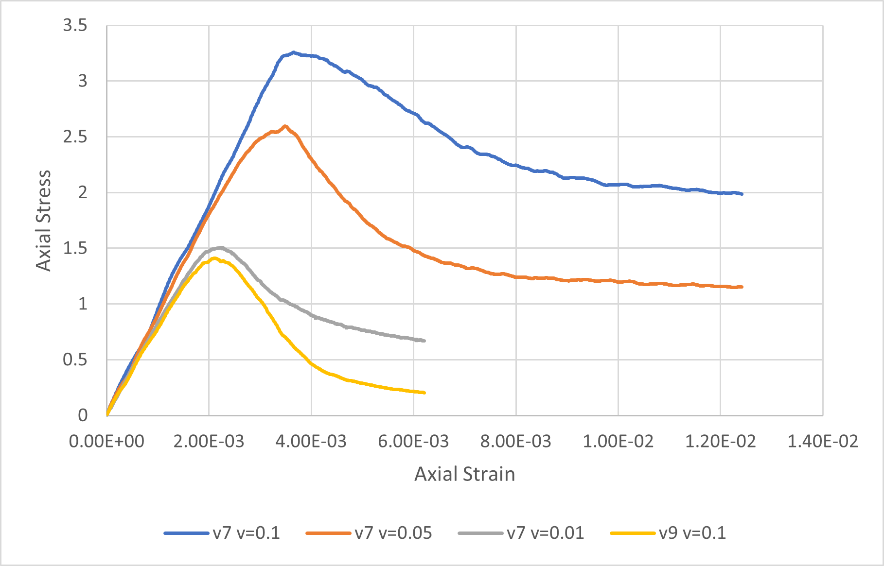
Figure 6: Comparison of 3DEC Version 7 results for different loading rates, and the results from this example run in Version 9.
Endnotes
| Was this helpful? ... | Itasca Software © 2024, Itasca | Updated: Apr 02, 2024 |
