Generating Zones
Zones in 3DEC are usually generated with commands. The basic commands are usually capable of meshing any block assembly with tetrahedra. The meshing is quite robust, but there are some drawbacks including lack of controls and slow generation in some cases. A new experimental method was added in Version 7 to address some of these issues. Both methods are descibed below.
In addition, Version 7 also added the ability to import zones from a different meshing program (e.g. Griddle). This is descibed in the Importing and Merging document.
Generating Zones with Commands
The basic command for generating tetrahedral zones in block zone generate edgelength. Different edge lengths may be specified for different blocks. Edge lengths must be constant within each blocks. If you require a gradation of zone sizes within a single block, you will need to cut the block into smaller blocks and joint them, or use the new zoning algorithms (New Zoning Commands).
Zones are not generatred until edge lengths have been specified for ALL blocks. Once zones have been generated, subcontacts are also created. Constitutitve models and properties for zones and contacts can then be assigned.
The example below shows how smaller zones can be created close to a region of interest (in this case, a load applied at the surface).
model new
block create brick -20 20 -20 20 -20 0
block densify segments 10 10 5 join
block create brick -4 4 -4 4 0 4

block zone generate edgelength 0.5 ...
  range position-x -8 8 position-y -8 8 position-z -4 4
; defining an edgelength length over a region that has already
; been assigned an edgelength length
;   will not overwrite the previously assigned edgelength length.
block zone generate edgelength 1 ...
  range position-x -16 16 position-y -16 16 position-z -8 0
block zone generate edgelength 2

Figure 1: Example of zoning with different edge sizes in different blocks.
The gridpoints across joints are guaranteed to match - as shown in Figure 1. This reduces discontinuities in stress across joint boundaries. For blocks with very bad geomtries, zoning may fail in some blocks. In this case you can use the alternate to relax the constraint and allow mismatched gridpoints across faces. Note that this will result in stress concentrations at these boundaries.
Even though the gridpoints will always match across joints, faces may not. It is possible to have matching gridpoints and mismatched faces (see Figure 2). For this reason, it is recoommended to have at least two zones across each dimension (see Figure 3). Alternatively, the new zone generation algorithms (New Zoning Commands) always ensure matching gridpoints AND faces.
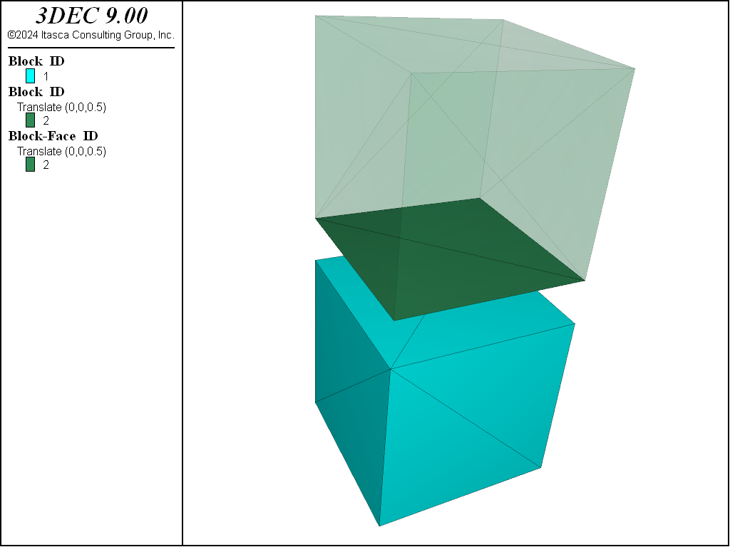
Figure 2: Example of mismatched faces in 2 zoned blocks. The top block is translated upwards and 5 sides made transparent for ease of viewing.

Figure 3: Example of matched faces when there are at least 2 zones across the block dimension.
The analysis of large models can also be aided by using the block zone generate center command, which
is a variation of the block zone generate edgelength command. This command allows the sizes of the tetrahedral
zones to be increased gradually, outward from a central point. There still must be a constant zone size within each block. This command is particularly useful in conjunction with the block create tunnel command.
New Zoning Commands
New zoning algorithms were added in Version 7 to address some of the shortcomings described above. These can be accessed with the block zone generate-new command. This is often preceded by the block zone size command, which is used to specify desired zone sizes in different parts of the model prior to zoning.
Unlike the block zone generate edgelength command, the block zone generate-new command can only be given once. Zone sizes are specified with keywords in this command, or previously with block zone size commands. Examples are given below.
Specifying Edge Length
With block zone generate-new, we can specify the global parameters for the whole model such as the range for zone size (max-edge, min-edge) and the gradation (gradation-surface, gradation-volume).
By defaut, the zone size is equal to one-tenth the diagonal length of the model as shown in the example below.
block create brick 0 1
block zone generate-new

Figure 4: Zoning of block with new zoning algorithms using default parameters.
We can set the mean edge length in the whole model by setting only max-edge or min-edge:
block create brick 0 1
block zone generate-new max-edge 0.5
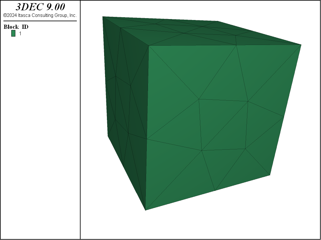
Figure 5: Zoning of 1x1x1 m block with new zoning algorithms specifying an edge length of 0.5.
The block zone size command is used to specify the ‘local’ zone size. We can specify the zone size for different parts in the model. Note that unlike the :kwd:block.zone.generate.edgelength` command, if the block zone size command is given multiple times for the same range, then the last one wins. This is consistent with how all of the other 3DEC commands work.
Note also that the gridpoints (and faces) will match across joint boundaries as shown in the figure below.
block create brick 0 1
block densify segment 2
block zone size edge 0.1 range pos-z 0.5 1
block zone size edge 0.3 range pos-z 0 0.5
block zone generate-new min-edge 0.1 max-edge 0.3
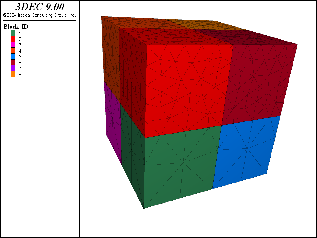
Figure 6: Zoning blocks with different zone sizes in different regions.
Non-Uniform Edge Length
Like the block zone generate command, the zone size can be made to increase gradually from the center as shown. However, unlike the block zone generate center comand, it is not necessary to split the model into separate blocks. The zone sizes can vary within a single block as shown:
block create brick -5 5 -1 1 -5 5
block zone size center 0,0,0 distance-1 0 edge-1 0.1 distance-2 5 edge-2 1
block zone generate-new min-edge 0.1 max-edge 1
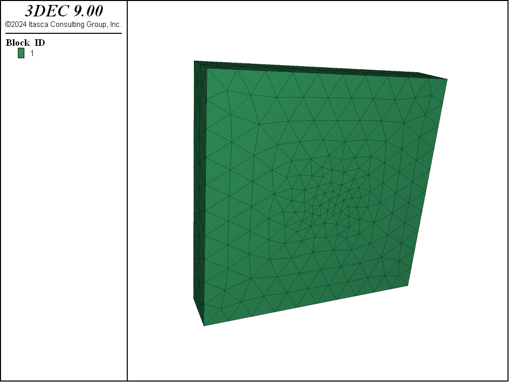
Figure 7: Zoning a block with zone size increaing from the center (cross section shown).
Isolated Points
It is also possible to specify the zone size near a particular gridpoint with the isolated-point keyword as shown. The gradient-surface keyword dictates the rate at which the zone size on the surfaces increases away from the specified point. A larger number means a faster gradation.
block create brick 0 1
block zone size isolated-point 0 0 0 edge 0.01
block zone generate-new min-edge 0.01 max-edge 0.2 grad-surface 0.5

Figure 8: Zoning a block with zone size specified at a gridpoint.
This also works if a point is specified inside of the block (not at a gridpoint).
block create brick 0 1
block zone size isolated-point 0.5 0.5 0.5 edge 0.01
block zone generate-new min-edge 0.01 max-edge 0.2 grad-surface 0.5
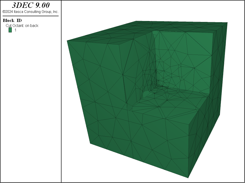
Figure 9: Zoning a block with zone size specified at a location inside of the block.
Using the “by” keyword
The block zone size command behaves differently depending on the element type following by keyword in the range:
by block-gridpoint: specify zone size for gridpoints in the range;by block-bface: specify zone size on faces in the range;by block: specify zone size inside blocks in the range (this is the default if no element is specified).
Note that for faces, you need to use by block-bface rather than by block-face. This refers to the original block faces before they are triangulated.
An example is given below.
block create brick 0 1
block create brick 2 3 0 1 0 1
block create brick 4 5 0 1 0 1

; In the first block, the zone size is uniform and equal to 0.2
block zone size edge 0.2 range pos-x 0 1
; In the second block, the zone size near the top face is set to 0.05
block zone size edge 0.05 range pos-x 2 3 pos-z 1 by block-bface
; In the third block, the zone size near the bottom left corner is set to 0.05
block zone size edge 0.05 range pos-x 4 pos-z 0 by block-gridpoint
;Now we set the zone size range for the whole model
block zone generate-new min-edge 0.05 max-edge 0.2
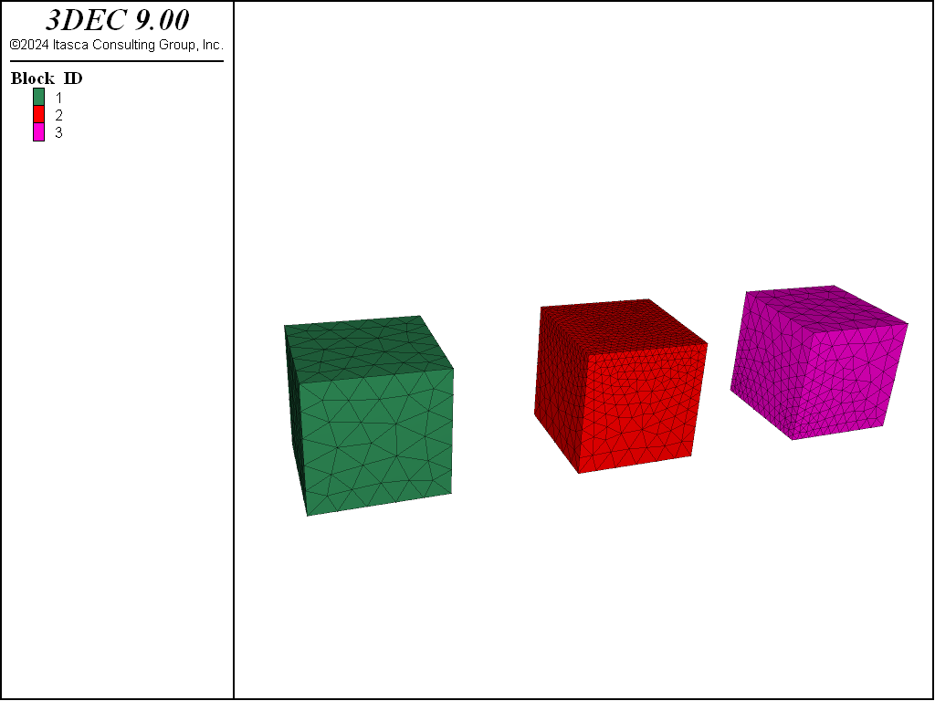
Figure 10: Example showing different ways to specify zone size.
block create brick -5 5 -5.0 5.0 -5 5
block cut joint-set spacing 1  ; bedding
block cut joint-set dip 60 dip-direction 270 origin 1.5 0 0

block face group 'hf' range plane dip 60 dip-direction 270 origin 1.5 0 0  dist 0.1

; small zones on the hydraulic fracture planes
block zone size edge 0.25 range group 'hf' by block-bface
block zone generate-new min-edge 0.25 max-edge 1

Figure 11: Model with an inclined fault and horizontal bedding meshed in Version 7. The bedding planes are not shown but can be seen on the cutting plane through the blocks.
In version 9, by default 5 control points are placed along each edge to ensure a constant zone size across the face. The same model run in Version 9 is shown in Figure 12
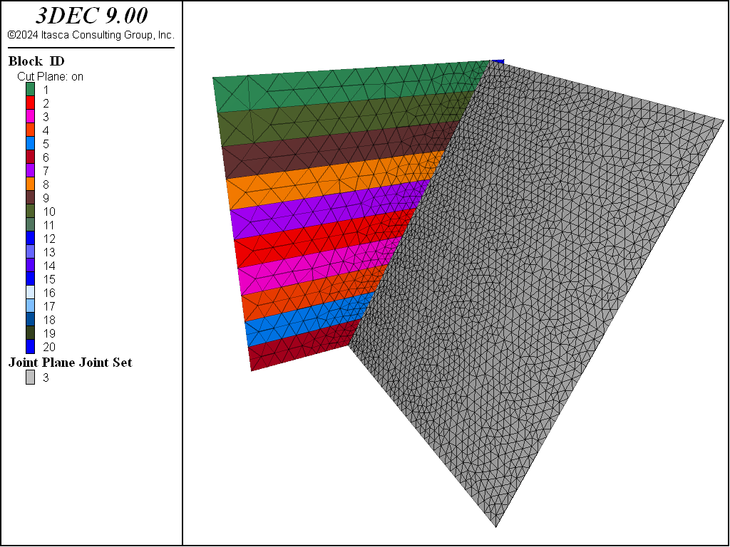
Figure 12: The same model meshed in Version 9.
The mesh can be improved further by adding more control points. If the last command is replaced with the following, then the mesh in Figure 13 results.
block zone generate-new min-edge 0.25 max-edge 1 num-control-point 10

Figure 13: The same model meshed with 10 control points.
Zoning Failure
The new zoning algorithms are less robust than the old logic. For blocks with very back geometries (face angles < 1^circle) it will fail to zone the blocks. In this case the only choice is to delete bad blocks and try again, or use the old logic. See Block Quality Metrics #blockmetrics for information on finding bad blocks.
The old zoning logic may also occasionally fail for bad block geometries. Here are some possible solutions:
Specify a smaller zone size for the blocks that did not zone with another
block zone generate edgelengthcommand.Split the blocks that did not zone using
block cutcommands and rezone. The rangedeformable notis useful for identifying the unzoned blocks.Delete the blocks that did not zone. This is generally only recommended for large-strain problems where the gaps will close.
Leave the unzoned blocks as rigid. Note that you cannot assign zone constitutive models or properties to these blocks.
| Was this helpful? ... | Itasca Software © 2024, Itasca | Updated: Apr 02, 2024 |
