Op: Creating a 2D Structural Element
The operations menu holds a command for creating a 2D structural element. It is enabled only when one or more faces are selected.
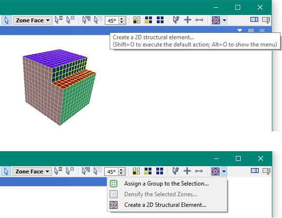
With a zone face selection in the Model pane, choosing the “Create a 2D Structural Element…” command ( ) shows a dialog for specifying element type and setting parameters.
Note that this dialog implements the structure shell create by-zone-face, structure liner create by-zone-face, and structure geogrid create by-zone-face commands.
New 2D structural elements can be created on the currently selected faces. Which elements—and parameters controlling their creation—can be entered into the dialog.
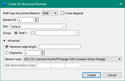
The “Shell-type-structured element:” selection determines which of the three currently available 2D structural element types to create — , , or .
If “Cross diagonal” is checked, four triangular elements will be created on each quadrilateral face using a node created at the centroid. Otherwise, two triangular elements will be created at each quadrilateral face across a diagonal.
If the “Liner” structural element is checked, a “Separate” option will be available. This will cause selected internal faces to be automatically separated before the liner elements are created between the two new surfaces.
The “Element ID” assigns the ID number used to identify groups of structural elements—elements with the same ID numbers will share nodes on creation.
The “Slot” determines what slot name will be used for the group assigned to the elements on creation.
The “Group” determines which group name (in the slot above) will be assigned to the element on creation. A default group name is assigned if nothing is specified here.
In the advanced section, a “Maximum edge length” may be specified. This automatically subdivides created elements until their edge length is less than the given value. Alternatively, selecting a “Segments” value greater than one causes every element to be subdivided along the edges that many times on creation. In general, using elements the same size as the zone face is sufficient.
The Finite-Element type used to implement the element may also be specified. Please see Shell Finite Elements for a detailed description. In general, elements attached to zone faces should use the default DKT-CST element type.
Lastly, if separation of internal faces is going to occur, “Side determination origin” is used to select which face is assigned a unique group name and is used to create the elements. In general, this does not make any difference for liners. This selection is done using an origin point—a seed face is picked on the side away from the origin point, and then subsequent faces are chosen to keep that side consistent.
| Was this helpful? ... | Itasca Software © 2024, Itasca | Updated: Apr 02, 2024 |
