Cantilever Beam with Applied Moment at Tip — Beam Elements
Problem Statement
Note
To view this project in FLAC2D, use the menu command . Choose “Structure/Beam/Cantilever” and select “Cantilever.prj” to load. The main data files used are shown at the end of this example. The remaining data files can be found in the project.
A cantilever beam is subjected to an applied moment at its tip, as shown in Figure 1. This problem is an example of geometric nonlinearity, whereby deformations significantly alter the location of loads, so that equilibrium equations must be written with respect to the deformed geometry. Such problems can be solved by running FLAC3D in large-strain mode. The large-strain \(y\)-direction deflection at the beam tip (assuming that the material remains linearly elastic) is given by Cook et al. (1989, pp. 529-531) as
where: |
\(E\) |
= |
Young’s modulus; and |
\(I\) |
= |
moment of inertia. |
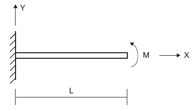
Figure 1: Cantilever beam with applied moment at tip.
Several properties and loading conditions are used in this example:
cross-sectional area (\(A\)) |
0.006 m3 |
Young’s modulus (\(E\)) |
200 GPa |
Poisson’s ratio (\(\nu\)) |
0.30 |
moment of inertia with respect to the out-of-plane axis (\(I\)) |
200 × 10-6 m4 |
beam length (\(L\)) |
10 m |
applied moment at tip (\(M\)) |
5 × 10⁶ N-m |
For these conditions, the theoretical tip deflection, \(v_{\rm tip}\), is given by equation (1) to be 5.477 m.
The FLAC2D model consists of 10 beam elements and 11 nodes. Boundary conditions corresponding to beam-theory behavior are imposed on all the nodes. The left end is fully fixed in all six degrees of freedom. And a moment vector aligned with the \(z\)-direction is applied to the node at the beam tip.
The final structural configuration is shown in Figure 2. The \(y\)-direction deflection at the beam tip equals 5.509 m, which is within 0.58% of the analytical solution.
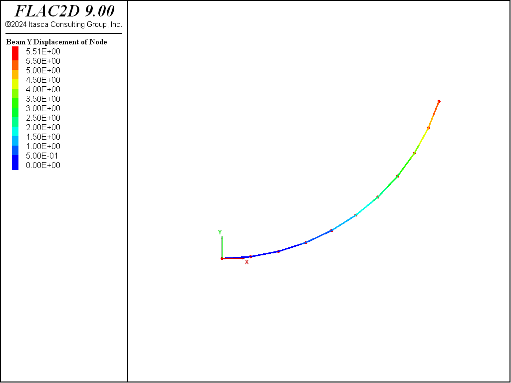
Figure 2: Final structural configuration.
Reference
Cook, R. D., D. S. Malkus and M. E. Plesha. Concepts and Applications of Finite Element Analysis, Third Edition. New York: John Wiley & Sons Inc. (1989).
Data File
Cantilever.dat
model new
model title ...
      'Cantilever beam, applied moment of 5e6 at tip (large-strain solution)'
; Create beam and assign properties
structure beam create by-line (0,0) (10,0) segments=10
structure beam property young=2e11 poisson=0.3
structure beam property cross-sectional-area=6e-3 moi=200e-6
; Boundary conditions
structure node fix velocity rotation range position-x 0     ;  fully fix left end
structure node apply moment=5e6 range position-x 10   ; apply moment at tip
; Run the model
model large-strain on
model solve ratio-local=1e-7
model save 'Cantilever'
| Was this helpful? ... | Itasca Software © 2024, Itasca | Updated: Apr 02, 2024 |
