Pane Elements
The Title Bar and Menu
The title bar has 3 or 4 buttons on the right side, depending on whether the pane is docked or floating.
Docked |
|
Floating |
|


The triangular button shows the Pane menu.
The second button hides the pane.
The third button in the floating title bar will maximize a pane or restore it to its previous size.
The last button closes the pane.
The Toolbar
As with any pane, the toolbar appears as the main toolbar adjacent to the program’s menu bar when the pane is active. In addition, the toolbar may be shown/hidden within the pane, just beneath its title bar, by pressing the button for the Pane menu on the Building Blocks title bar and selecting “Show Toolbar.”
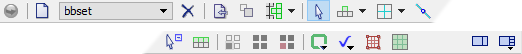
The tools have the following meanings.
Icon |
Command/Mode |
Description/Comment |
|---|---|---|
|
Execute/Stop toggle |
Execute or stop cycling; see the Toolbar topic for more information. |
|
Add a new set… |
Creates a new set of building blocks. |
(list) |
Sets |
This is a list of all the building block sets. The currently active set is displayed. Choosing a different set from the list will make it the current, active set displayed in the pane. |
|
Delete the current set |
Deletes the currently active set of building blocks. |
|
Import geometric data… |
Imports a set of geometric data, which could be a .DXF, .STL, or .GEOM file. See Importing Geometric Data |
|
Generate from geometry… |
Generates either zones or building blocks from the geometric data that’s loaded into the current set of building blocks. See Generating Zones or Blocks From Geometric Data |
|
Import blocks… |
Imports blocks from a saved set of blocks. |
|
Selection mode |
This tool is used to select and manipulate objects. It is the default mode for the mouse to be in. See Selection and Manipulation of Objects. Right-click the tool button to see a page describing view manipulation controls — the same controls as are used in a plot pane. |
|
Add Blocks mode |
This tool is used to add new blocks to existing blocks. See Adding Blocks |
|
Split Blocks mode |
This tool is used for splitting blocks. See Splitting Blocks |
|
Control Point mode |
This tool is for adding and manipulating control points. See Curved Edges and Control Points |
|
Hide Blocks mode |
In this mouse mode, click a block to hide it. |
|
Add a layer… |
After selecting one or more faces, click this tool button to add a layer of blocks to the selected faces; or use the Alt key and drag the reference point off the selection and click this tool button to add blocks rotated around an axis. |
|
Show only selected blocks |
After selecting one or more blocks, click this tool to hide all the unselected blocks. |
|
Show all blocks |
Click this button to make all the blocks visible. |
|
Show bad blocks |
If the model has any invalid blocks, this button will become enabled. Clicking it will cause enough good blocks to be hidden for you to be able to see the bad blocks that may be buried inside the model. |
|
Highlight groups |
After you have assigned groups to points, edges, faces or blocks, this menu will hold commands to highlight (in green) any group(s) you choose. There is also a command to show all the blocks and only the blocks in the specified group(s). See Highlighting Groups |
|
Validate |
This menu holds commands to help ensure the model is valid. See Validating the Model |
|
Autozone… |
This command presents options for applying automatic zoning to the model. |
|
Generate zones |
This command creates zones from the building blocks. The zones can be viewed in the Model pane or a plot pane. |
|
Show/Hide Control Panel |
Toggle display of the Control Panel. See the Toolbar topic for more information. |
|
Show/Hide Control Sets |
This button is a pull-down that lists the available control sets for this pane type; select an unchecked item to display it in the control panel, select a checked item to hide it. See the Toolbar topic for more information. |


View Manipulation
the R and Ctrl+R keys work as they do in the plot window to reset the view
the right mouse button rotates the view
the mouse wheel zooms in and out
press and hold the right mouse button and then the left mouse button to drag the view up/down/left/right; or use the Shift key with the right mouse button
See the View Manipulation Quick Reference for more information.
The ESC Key
In general, the ESC key cancels the current operation and puts the mouse back into selection mode. The ESC key will cancel mouse dragging, point-to-point snapping, escape out of Add Blocks mode and so on.
The Status Bar
The main window’s status bar shows controls and information related to the Building Blocks pane.

One of the features of the status bar is that, when you select two points, it will tell you the distance between those points. And if you select an edge, it will tell you the distance between the end points of the edge.
“View Tolerance” is a tolerance level based on the current zoom level of the view and the size of the points as specified in the View control set. It’s the approximate radius of the points shown on screen.
Here is a description of the Surface/Deep and Perspective/Parallel Modes.
The indicator next to the corner of the status bar shows whether navigation is in regular mode or first-person mode. Using regular navigation, the mouse wheel zooms in to the center point of the view or to the location on an object that the mouse is over. In first-person mode, the mouse wheel adjusts the view as if you were walking through the model. To use first-person navigation, hold down the Alt key while using the mouse wheel. (In Parallel projection mode, first-person navigation has no effect.)

Figure 1: Regular navigation.

Figure 2: First-person navigation.
| Was this helpful? ... | Itasca Software © 2024, Itasca | Updated: Apr 02, 2024 |
