Points and Edges
Creating Points and Edges
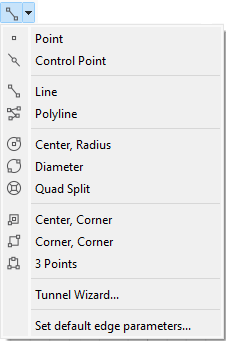
Figure 1: The Point/Edge Tools on the Sketch tool bar.
Create Points
 Using the Point Tool
Click to set a point at the desired location.
 Using the Line Tool
Click to set a point at a desired location, then click it again.
Using the Keyboard
Press spacebar and enter coordinates for the desired point. FISH symbol(s) may also be used.
Moving Points
Using the Mouse
Select and drag a point to the desired location.
Entering Coordinates
Merging Points
Select and drag one point onto another to merge the points. Pressing the shift key while dragging a point will prevent merging.
Create, Add to, or Split Edges
Using the Line Tool
Any of the following methods will produce a new edge or edges.
[Create] Click a location, move the mouse to the intended endpoint, click.
[Join Points] Click an existing free point, move to another existing free point, click.
[Add to] Click an existing edge endpoint, move the mouse to the intended location, click to add an attached new edge to the starting edge.
[Split] Click on an existing edge to split the edge in two at that point.
Constraining — When using the Line tool, press ctrl to constrain the angle of the edge to 15º increments. The default value is 15º but can be changed in the “Sketch” panel of the Options dialog.
Suspend Snapping — Press shift while using the tool to prevent object snapping (this keeps the mouse from snapping to/onto objects that it approaches).
 Using the Polyline Tool
Click a location to start; click at succeeding location(s) to add to the line; double-click to terminate.
The polyline tool will create, join points, add to existing edges, or split edges in the same manner as the Line tool.
Create Curved Edges
 Using the Control Point Tool
Click a location on an edge to add a control point at that location, and move the point to the desired location by:
Keeping the left mouse button pressed when placing it and dragging it to the desired location.
Releasing the left mouse button at placement, then click-and-dragging on the point (right- or left-mouse button will work for this) to the desired location.
At this point, the control point will serve to curve the edge. However, all edges are created as “line”-type edges by default (the default may be changed in the “Sketch” panel of the Options dialog). To obtain a curve, the “Edge Type” property of the edge must be changed to “curve” (either right-click the selected edge and choose Edit Edge Properties or select the edge and set the property in the “Object Properties” in the Tools area).
Figure 2: Once an edge has one or more control points on it, obtaining a curved shape from the edge requires changing its “Edge Type” property to “curve”.
Deleting Points and Edges
Points
Select one or more points and press the Delete key. Note the edges connected to the points are deleted as well.
Edges
Select one or more edges and press the Delete key. Note the points at the ends of the deleted edges are not deleted.
Tips
Points are Automatically Added at Edge Intersections
Where edges meet, a point must mark the location where they do. As a result, when using the Line or Polyline tool, if one edge is drawn across another, a point will automatically be added at the intersection of the edges.
Figure 3: When edges are drawn across each other, a point is automatically added at their intersection.
Using the Right Mouse Button
Bear in mind that when the line tool () or the control point tool () is active, the regular selection functions of the select tool ( ) are available on the right mouse button, as described in Right-Click Selection Overload.
Edge Zoning
Main Zoning Properties
The edge properties “Zone Size”, “Zone Length”, and “Ratio” will all affect the zoning produced from an edge. These are set/changed using normal object property editing methods.
Zone Size
This setting determines the number of zones to be created along the edge. Locations of expected zone edges are demarcated with red “x” marks along the edge. Setting this property will override an existing zone length assignment.
Zone Length
This setting specifies an exact length for zones along the edge. When used, the edge will be split into an integer-expressed number of zones that are closest in size to the value provided. Setting this value will override an existing zone size property.
Ratio
Specify a distribution of zone sizes along the edge using a ratio. A ratio of 1.1 means that each zone succeeding zone size in the direction of application will be 1.1 times the length of the previous zone. If not specified, the default ratio is 1.0. Use the “Reverse” button adjacent to the value field to set the ratio in the opposing direction.
Changing the Zoning Defaults
Any newly created edge is given default zoning of four zones per edge. This is the program default. It may be changed in the “Default Edge Parameters” dialog, which is accessed from the Point/Edge Tools menubutton item “Set default edge parameters…” (see the image at top).
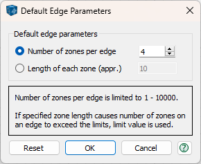
Number of Zones per Edge
Select this option to input a new default number of zones (within 1 - 10000) for new edges. Changing this value will not affect existing edges.
Length of Each Zone (appr.)
Select this option to input the length of each zone (within 1.0e-5 - 1.0e5) for new edges. This value will be approximate to allow fitting a whole number of zones per edge. The initial default value when starting the application is 10. Changing this value will not affect existing edges.
If the specified zone length causes the number of zones on an edge to exceed the limits (1 - 10000), the limit value is used for the edge.
See Also
In addition to setting zoning along edges, as described above, zoning within a block may be affected by the block property zone multiplier, or by the operation of the automatic zoning tool. Refer to the topics below for more information.
Advanced Edge Operations
Creating Edges from Background Geometry
A geometric data file (e.g. DXF, GEOM, STL files) imported into a sketch set contains numeric information that may be used to create sketch edges conforming to the background geometry. This can be done manually or automatically.
Manual Edge Creation
Use the “Line” or “Polyline” tool to “trace” the geometry, as illustrated in Snap-To Behavior on Background Geometry.
Automatic Edge Creation
Press the Automatically Create Edges button (
). When using the latter option, edges are created for every edge found in the background geometry. The tool is only enabled when a background geometry is present; it is disabled otherwise.
When automatically creating edges from a background geometry, the maximum zoning on an edge is 1000, even if the default edge parameters are set to more than 1000 zones. This is done for faster data processing and to avoid unnecessary memory consumption. If the number of zones on any automatically created edge is reduced to 1000, a warning message will be shown. The number of zones can later be changed individually for each edge in the Object Properties dialog or for all edges by using Automatic Zoning.
Note that a curved edge in the background geometry is represented by a number of straight segments. Sketch set edges are created along the segments. These edges can later be combined into a single curved edge as outlined below.
Selecting Edges by Break Angle
To select a number of connected edges at once: press the “Select edges by break angle” button ( ) on the toolbar, and click on an edge. All connected edges within the specified break angle (the angle between any two edges) will be selected. The selection also stops if an edge is connected to more than one other edge at an endpoint.
The “Select edges by break angle” tool is persistent; the mouse will stay in that mode until the tool button is pressed again to toggle the tool off. The break angle is specified using the edit field adjacent to the tool button.
Combining Edges
A set of connected edges may be combined into a single curved edge (represented by Cubic Hermite spline). This operation performed with the “Combine selected edges” tool ( ). Selected edges will be replaced with a single curved edge that may contain multiple control points (used to specify local curvature).
To refine the new curve’s approximation of the original edges, adjust the tolerance for combining edges (click the tool’s  button to access “Curve Tolerance…”). The tolerance affects the number of control points on the new edge and therefore local curvature. The smaller the tolerance, the more the new edge will mimic the original geometry, but it may have a large number of control points.
“Combine selected edges” tool is enabled only when two or more connected and unsplit edges are selected.
The animated image below shows an example of a workflow for automatically creating edges from the background geometry while using a specific default zone length and combining tolerance.
Figure 5: Edge creation: edges are generated automatically from a geometry, then three successive curve-type edges are built by first selecting a group of edges by break angle and then combining the selected edges.
| Was this helpful? ... | Itasca Software © 2024, Itasca | Updated: Apr 02, 2024 |
