zone face apply command
Syntax
- zone face apply keyword <range>
Primary keywords:
acceleration acceleration-dip acceleration-local acceleration-normal acceleration-strike acceleration-tangential acceleration-x acceleration-y acceleration-z convection discharge flux head leakage pore-pressure quiet quiet-dip quiet-normal quiet-strike quiet-tangential reaction reaction-dip reaction-local reaction-normal reaction-strike reaction-tangential reaction-x reaction-y reaction-z stress-dip stress-normal stress-shear stress-strike stress-xx stress-xy stress-xz stress-yy stress-yz stress-zz temperature velocity velocity-dip velocity-local velocity-normal velocity-strike velocity-tangential velocity-x velocity-y velocity-z
Note
- The following nomenclature / equivalence between FLAC3D and FLAC2D is used:
Zone faces = zone surface faces in 3D or zone edges (lines connecting gridpoints) in 2D
There is no 2D equivalence for 3D zone edges
3D volumes <-> 2D areas
Zone face surface area in 3D <-> Zone face length in 2D
This command is used to apply boundary conditions at surface faces of the model. To apply conditions to zones rather than at faces, see the
zone applycommand. To apply conditions at individual gridpoints, see thezone gridpoint fixcommand.The user must specify the condition type, the numerical value or values associated with it, optional modifiers that may vary the value over time and space, and an optional
rangeover which the boundary condition is to be applied. If no range is specified, then the command applies to the entire model.To remove a boundary created with this command, see
zone face apply-remove.After the supplied condition’s value(s), an optional modifier keyword can be used to modulate the supplied value. These are marked <[faceapplyblock]> in the commands, with definitions found in the “Keyword Block” section at the end of this topic.
Note that some apply conditions (like velocity) are actually applied to the gridpoints attached to all the faces in the range. This could cause a conflict between gridpoints that are connected to multiple faces with conflicting apply conditions specified. Whenever possible, FLAC will attempt to satisfy all conditions — including automatically adjusting the gridpoint local axes system to accommodate the constraints. If this is not possible, however, the velocity condition applied last will dominate.
Note
Occasionally you may want to apply a condition to a set of internal faces. To do this, we recommend temporarily nulling out one side with the
zone cmodel assigncommand, applying the condition, and then restoring the zones to their original constitutive model. This will allow the apply logic to select the appropriate orientation when necessary — for applying stress boundary conditions, for example.- acceleration v <[faceapplyblock]>
Vector of the acceleration components applied in the global coordinate axes (available only if
model configure dynamichas been specified). This is a gridpoint based condition.
- acceleration-dip f <[faceapplyblock]>(3D ONLY)
Acceleration component applied in the dip direction of the local gridpoint axes — available only if
model configure dynamichas been specified (see Local Axes System below). This is a gridpoint based condition.
- acceleration-local v <[faceapplyblock]>
Vector of the acceleration components applied in the local gridpoint axes — available only if
model configure dynamichas been specified (see Local Axes System below). This is a gridpoint based condition.
- acceleration-normal f <[faceapplyblock]>
Acceleration component applied in the normal direction of the local gridpoint axes — available only if
model configure dynamichas been specified (see Local Axes System below). This is a gridpoint based condition.
- acceleration-strike f <[faceapplyblock]>(3D ONLY)
Acceleration component applied in the strike direction of the local gridpoint axes — available only if
model configure dynamichas been specified (see Local Axes System below). This is a gridpoint based condition.
- acceleration-tangential f <[faceapplyblock]>(2D ONLY)
Acceleration component applied in the tangential direction of the local gridpoint axes — available only if
model configure dynamichas been specified (see Local Axes System below). This is a gridpoint based condition.
- acceleration-x f <[faceapplyblock]>
\(x\)-component of acceleration applied at a gridpoint — available only if
model configure dynamichas been specified. This is a gridpoint based condition.
- acceleration-y f <[faceapplyblock]>
\(y\)-component of acceleration applied at a gridpoint — available only if
model configure dynamichas been specified. This is a gridpoint based condition.
- acceleration-z f <[faceapplyblock]>(3D ONLY)
\(z\)-component of acceleration applied at a gridpoint — available only if
model configure dynamichas been specified. This is a gridpoint based condition.
- convection f1 f2 <[faceapplyblock]>
A thermal convective boundary condition is applied over the range of faces specified (available only if
model configure thermalhas been specified). f1 is the temperature Te of the medium to which convection occurs. f2 is the convective heat transfer coefficient h (e.g., in W/m2◦ C).
- discharge f <[faceapplyblock]>
Fluid flux f is the component of the specific discharge vector (e.g., in m/s) applied normal to the boundary.
- flux f <[faceapplyblock]>
A flux is applied over the range of faces specified (available only if
model configure thermalhas been specified). f is the initial flux (e.g., in W/m2). This command is used to specify a constant flux into (f > 0) or out of (f < 0) a thermal boundary of the grid. Decay of the flux can be represented by applying a time-varying modifier available in <[faceapplyblock]>.
- head f <[faceapplyblock]>
Uses Head to calculate and appliy a specific pore-pressure value (available only if
model configure fluidhas been specified). Fluid Density and Gravity need to be previously defined. This is a gridpoint based condition.
- leakage f1 f2 <[faceapplyblock]>
f1 is the pore pressure in the leaky layer.
f2 is the leakage coefficient, h (e.g., in m3/N sec).
See this equation in Fluid Flow Boundary and Initial Conditions in FLAC3D for the formula for a leaky boundary condition. A leaky condition is applied over the range of faces specified. The history keyword is not active for leakage.
- pore-pressure f <[faceapplyblock]>
Applies a specific pore-pressure value (available only if
model configure fluidhas been specified). This is a gridpoint based condition.
- quiet <[faceapplyblock]>
Quiet (viscous) boundary applied in all direction of the local gridpoint axes — available only if
model configure dynamichas been specified (see Local Axes System below).
- quiet-dip <[faceapplyblock]>(3D ONLY)
Quiet (viscous) boundary applied in the dip direction of the local gridpoint axes — available only if
model configure dynamichas been specified (see Local Axes System below).
- quiet-normal <[faceapplyblock]>
Quiet (viscous) boundary applied in the normal direction of the local gridpoint axes — available only if
model configure dynamichas been specified (see Local Axes System below).
- quiet-strike <[faceapplyblock]>(3D ONLY)
Quiet (viscous) boundary applied in the strike direction of the local gridpoint axes — available only if
model configure dynamichas been specified (see Local Axes System below).
- quiet-tangential <[faceapplyblock]>(2D ONLY)
Quiet (viscous) boundary applied in the tangential direction of the local gridpoint axes — available only if
model configure dynamichas been specified (see Local Axes System below).
- reaction <[faceapplyblock]>
Vector of all components of reaction force at a gridpoint Reaction forces will only be applied in directions that are currently fixed, and those fixity conditions will be removed. This is a gridpoint based condition.
- reaction-dip <[faceapplyblock]>(3D ONLY)
Reaction force in the dip direction of the local gridpoint axes Reaction forces will only be applied in directions that are currently fixed, and those fixity conditions will be removed. This is a gridpoint based condition.
- reaction-local <[faceapplyblock]>
Apply a reaction force in all components of the local coordinate system (see Local Axes System below). Reaction forces will only be applied in directions that are currently fixed, and those fixity conditions will be removed. This is a gridpoint based condition.
- reaction-normal <[faceapplyblock]>
Reaction force in the normal direction of the local gridpoint axes (see Local Axes System below). Reaction forces will only be applied in directions that are currently fixed, and those fixity conditions will be removed. This is a gridpoint based condition.
- reaction-strike <[faceapplyblock]>(3D ONLY)
Reaction force in the strike direction of the local gridpoint axes (see Local Axes System below). Reaction forces will only be applied in directions that are currently fixed, and those fixity conditions will be removed. This is a gridpoint based condition.
- reaction-tangential <[faceapplyblock]>(2D ONLY)
Reaction force in the tangential direction of the local gridpoint axes (see Local Axes System below). Reaction forces will only be applied in directions that are currently fixed, and those fixity conditions will be removed. This is a gridpoint based condition.
- reaction-x <[faceapplyblock]>
\(x\)-component of reaction force at a gridpoint Reaction forces will only be applied in directions that are currently fixed, and those fixity conditions will be removed. This is a gridpoint based condition.
- reaction-y <[faceapplyblock]>
\(y\)-component of reaction force at a gridpoint Reaction forces will only be applied in directions that are currently fixed, and those fixity conditions will be removed. This is a gridpoint based condition.
- reaction-z <[faceapplyblock]>(3D ONLY)
\(z\)-component of reaction force at a gridpoint Reaction forces will only be applied in directions that are currently fixed, and those fixity conditions will be removed. This is a gridpoint based condition.
- stress-dip f <[faceapplyblock]>(3D ONLY)
Stress component applied in the dip direction of the local face axes (see Local Axes System below).
- stress-normal f <[faceapplyblock]>
Stress component applied in the normal direction of the local face axes (see Local Axes System below).
- stress-shear f <[faceapplyblock]>(2D ONLY)
Stress component applied in the shear (tangential) direction of the local face axes (see Local Axes System below).
- stress-strike f <[faceapplyblock]>(3D ONLY)
Stress component applied in the strike direction of the local face axes (see Local Axes System below).
- stress-xx f <[faceapplyblock]>
xx-component of the stress tensor applied at a face
- stress-xy f <[faceapplyblock]>
xy-component of the stress tensor applied at a face
- stress-xz f <[faceapplyblock]>(3D ONLY)
xz-component of the stress tensor applied at a face
- stress-yy f <[faceapplyblock]>
yy-component of the stress tensor applied at a face
- stress-yz f <[faceapplyblock]>(3D ONLY)
xz-component of the stress tensor applied at a face
- stress-zz f <[faceapplyblock]>(3D ONLY)
zz-component of the stress tensor applied at a face
- temperature f <[faceapplyblock]>
Fixes and applies a specific temperature value to the gridpoint (available only if
model configure thermalhas been specified). This is a gridpoint based condition.
- velocity v <[faceapplyblock]>
Vector of all velocity components in the global coordinate axes. This is a gridpoint based condition.
- velocity-dip f <[faceapplyblock]>(3D ONLY)
Velocity component applied in the dip direction of the local gridpoint axes (see Local Axes System below). This is a gridpoint based condition.
- velocity-local v <[faceapplyblock]>
Vector of all velocity components in the local coordinate axes (see Local Axes System below). This is a gridpoint based condition.
- velocity-normal f <[faceapplyblock]>
Velocity component applied in the normal direction of the local gridpoint axes (see Local Axes System below). This is a gridpoint based condition.
- velocity-strike f <[faceapplyblock]>(3D ONLY)
Velocity component applied in the strike direction of the local gridpoint axes (see Local Axes System below). This is a gridpoint based condition.
- velocity-tangential f <[faceapplyblock]>(2D ONLY)
Velocity component applied in the tangential direction of the local gridpoint axes (see Local Axes System below). This is a gridpoint based condition.
- velocity-x f <[faceapplyblock]>
\(x\)-component of velocity applied at a gridpoint This is a gridpoint based condition.
- velocity-y f <[faceapplyblock]>
\(y\)-component of velocity applied at a gridpoint This is a gridpoint based condition.
- velocity-z f <[faceapplyblock]>(3D ONLY)
\(z\)-component of velocity applied at a gridpoint This is a gridpoint based condition.
Local Axes System
The local face axes are defined by the normal to the face. The dip, strike, and normal directions form a right-handed coordinate system. Given the normal vector, the other local axes are defined by “\(d\)-axis,” which points downward (i.e., in the negative \(z\)-direction) along the dip-direction, and “\(s\)-axis,” which is horizontal (i.e., lies within the \(xy\)-plane) such that \(d-s-n\) form a right-handed system as illustrated here.
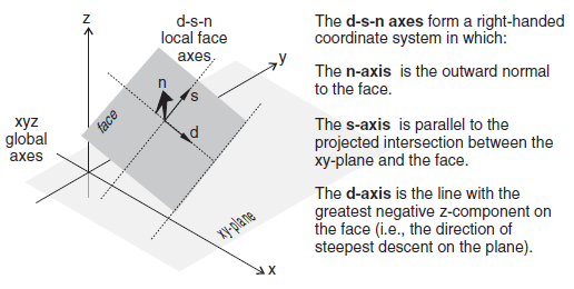
Figure 1: Local face axes.
zone face apply Keyword Block
The following keywords may be used to modify a supplied value. If the description of the modifier keyword mentions what type of value it may be applied to (e.g. scalar value, vector value, etc.), be sure there is a match between the modifier and the main keyword value. The commands main keywords are: acceleration, acceleration-dip, acceleration-local, acceleration-normal, acceleration-strike, acceleration-tangential, acceleration-x, acceleration-y, acceleration-z, convection, discharge, flux, head, leakage, pore-pressure, quiet, quiet-dip, quiet-normal, quiet-strike, quiet-tangential, reaction, reaction-dip, reaction-local, reaction-normal, reaction-strike, reaction-tangential, reaction-x, reaction-y, reaction-z, stress-dip, stress-normal, stress-shear, stress-strike, stress-xx, stress-xy, stress-xz, stress-yy, stress-yz, stress-zz, temperature, velocity, velocity-dip, velocity-local, velocity-normal, velocity-strike, velocity-tangential, velocity-x, velocity-y and velocity-z.
- break-angle f
Note: Only applies to gridpoint based apply items that require a local coordinate system (velocity, acceleration, reaction). Specify the angle between adjacent faces at which the boundary is treated as continous or as a corner. The default break angle is 45 degrees for a zero value condition and 90 degrees for a non-zero value condition.
- fish s
Specify a multiplier that is a FISH function named s. See the section FISH Callback Events for a discussion of FISH callbacks. The returned value of this FISH function is multiplied by the base value (including gradient) over all zone faces or gridpoints included in this apply condition. So a return value of 1.0 will apply the base value provided, and a return value of 0.0 will effectively remove it. This function will be called every step. If the apply condition requires a vector value, this function should also return a vector. If the apply condition requires two values, the function should return a vector and the \(z\)-component will be ignored.
- fish-local s
Specify a multiplier that is a FISH function named s, which is applied separately to each individual zone face or gridpoint affected by this apply condition. See the section FISH Callback Events for a discussion of FISH callbacks. This function must take at least one argument. For apply conditions that work directly on faces, the first argument is a pointer to the zone and the second argument is an integer from 1 to 6 (in 3D) and 1 to 4 (in 2D) indicating the face. For apply conditions that work on gridpoints, the first argument is a pointer to the gridpoint and the second argument is not used. This allows an apply condition to vary over time as well as space. The returned value of this FISH function is multiplied by the base value (including gradient) on the specific zone supplied. So a return value of 1.0 will apply the base value provided, and a return value of 0.0 will effectively remove it. This function will be called every step for every zone included in the apply condition. If the apply condition requires a vector value, this function should also return a vector. If the apply condition requires two values, the function should return a vector and the \(z\)-component will be ignored.
- gradient v
Apply a gradient to the scalar-value provided. This is not available if the apply conditions requires two values or a vector value.
- servo keyword ...
Use a servo tied to the mechanical convergence ratio to control the magnitude of the applied condition. This can be used to maintain, gradually ramp up, or gradually reduce apply conditions while maintaining a quasi-static response. This controls a factor that is multiplied with the base value supplied. By default the factor will start at 0.001, and will gradually increase to 1.0 as the convergence ratio falls below 2e-3, and decrease if it rises above 1e-2. The following keywords are available to control the servo response:
- latency i
The minimum number of steps that must pass since the last servo adjustment before the next one occurs. This can keep the servo from over controlling in the initial response to a change in the factor. The default value is 1.
- lower-bound f
Set the lower mechanical convergence ratio limit. If the current ratio falls below this limit, the factor will be multiplied by the lower-multiplier. The default limit is 2e-3.
- lower-multiplier f
If the current ratio falls below the lower-bound limit, the factor is multiplied by this number. The default is 1.01.
- ramp
Sets the servo into ramp mode. This means that the factor is not allowed to go down, the value will only increase. This is useful to gradually increase an applied condition to it’s full value. See also the reduce keyword.
- ratio keyword
Which mechanical convergence ratio is compared against lower-bound and upper-bound. By default this is the current value assigned by the
zone ratiocommand (which is average by default. See thezone ratiocommand for definitions. The available keywords are:
- average
Use the average mechanical force ratio.
- maximum
Use the maximum mechanical force ratio.
- local
Use the local mechanical force ratio.
- reduce
Sets the servo into reduce mode. In this mode the starting value of the factor is 1.0, and the minimum value is set to 0.0. When the current ratio falls below lower-bound the factor is reduced by the upper-multiplier. The factor is never increased. This is useful to gradually decrease an applied condition to zero.
- symmetry keyword ...
Note: Only applies to gridpoint based apply items that require a local coordinate system (velocity, acceleration, reaction). Indicates that certain planes should be treated as symmetry boundaries, and that the local direction chosen for the apply condition should automatically be adjusted to respect that. The following keywords are currently available to specify 1 to 3 symmetry planes:
- x f
Indicates that the plane x=value is a symmetry plane. The local direction calculated for grid-points on that plane will have no x-component.
- y f
Indicates that the plane y=value is a symmetry plane. The local direction calculated for grid-points on that plane will have no y-component.
- z f (3D ONLY)
Indicates that the plane z=value is a symmetry plane. The local direction calculated for grid-points on that plane will have no z-component.
- table s <time keyword>
Specify a multiplier that is a table named s. By default the x-axis value is the current step number. The optional time keyword may be used to specify which processes accumulated time-total should be used to provide the x-axis value. The available keywords are:
- creep
- dynamic
- fluid
- mechanical
- step
- thermal
- update-direction b
Note: Only applies to gridpoint based apply items that require a local coordinate system (velocity, acceleration, reaction). If set to off, indicates that the local direction calculated for the grid point should not be updated later. It will stay the same even if the local zone geometry is modified, or if the mesh deforms in large strain. The default value is on.
- vary v
Apply a linear variation to the scalar-value provided. This is not available if the apply conditions requires two values or a vector value.
[DR: is location of local axes here ok, or should it be elsewhere? And, is more material needed?
| Was this helpful? ... | Itasca Software © 2024, Itasca | Updated: Apr 02, 2024 |
