Examples • Example Applications
Excavation and Support of a Shallow Tunnel (FLAC3D)
Problem Statement
Note
To view this project in FLAC3D, use the menu command . Choose “ExampleApplications/ ExcavationAndSupport” and select “ExcavationAnd… .prj” to load. The project’s main data file is shown at the end of this example.
A shallow tunnel is excavated in soft ground in an urban area. It is important to minimize the impact of the tunnel on existing structures and services. Surface settlements will depend on both the excavation method and the type of tunnel reinforcement. The surface settlement resulting from an advancing tunnel is very much a three-dimensional problem. Special three-dimensional considerations, which include the proximity of the ground surface and the effects at the end of the tunnel, are taken into account.
Surface settlement is calculated for the following construction method. The method applies a combination of support measures to reinforce the rock ahead of the tunnel face. The components of the method are:
excavation of a 3 m cut;
installation of a steel arch support;
construction of a 4 m long, 22 cm thick angled slot above the tunnel and filled with concrete to act as a pre-support shield;
installation of a shotcrete lining between steel supports; and
installation of horizontal cable bolts in the tunnel face.
A thick concrete liner is installed behind the advancing tunnel face. Figure 1 illustrates the components of the method. In order to evaluate the influence of the support method on surface settlement, every component should be simulated by the numerical analysis.
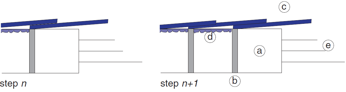
Figure 1: Components of the tunnel support method.
Modeling Procedure
A vertical plane of symmetry through the center of the tunnel is assumed, and only one-half of the tunnel is modeled. A 50 m length of the tunnel is represented in the model; the floor of the tunnel is located 39.5 m below the ground surface. A system of coordinate axes is defined with the origin at the floor of the tunnel; the \(z\)-axis points upward and the \(y\)-axis points along the axis of the tunnel. The FLAC3D grid is shown in Figure 2. The model contains approximately 15,000 zones; 50 zones are located along the axis of the tunnel.
The tunnel is constructed in a weak rock that is modeled as a Mohr-Coulomb material with a cohesion of 50 kPa and a friction angle of 20°. The mass density of the material is 2200 kg/m3.
The initial stress state corresponds to gravitational loading with the following relation between vertical and horizontal stresses: \(σ'_{zz}\) = \(σ'_{xx}\) = 2.0\(σ'_{yy}\).
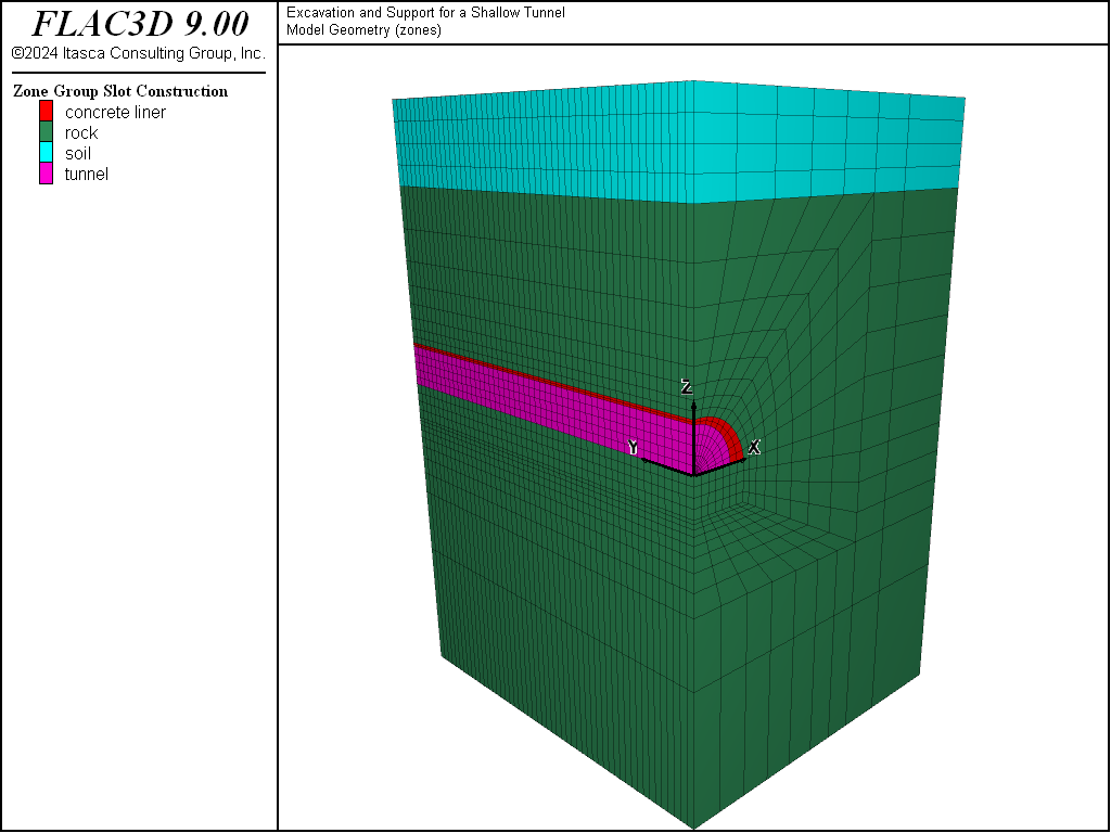
Figure 2: Tunnel model grid.
The pre-support concrete and shotcrete are modeled with shell structural elements, while the concrete tunnel lining is modeled with zones (the thickness of the concrete lining is large compared to the radius of the tunnel) that are assigned properties representing the lining material. The FLAC3D zones provide a reasonable approximation for bending of thick liners, because each zone consists of two overlays of five tetrahedral subzones. Figure 3 shows the shell structural elements that represent the pre-support concrete and shotcrete (after excavation of 30 m of the tunnel). The concrete lining is shown in Figure 4.
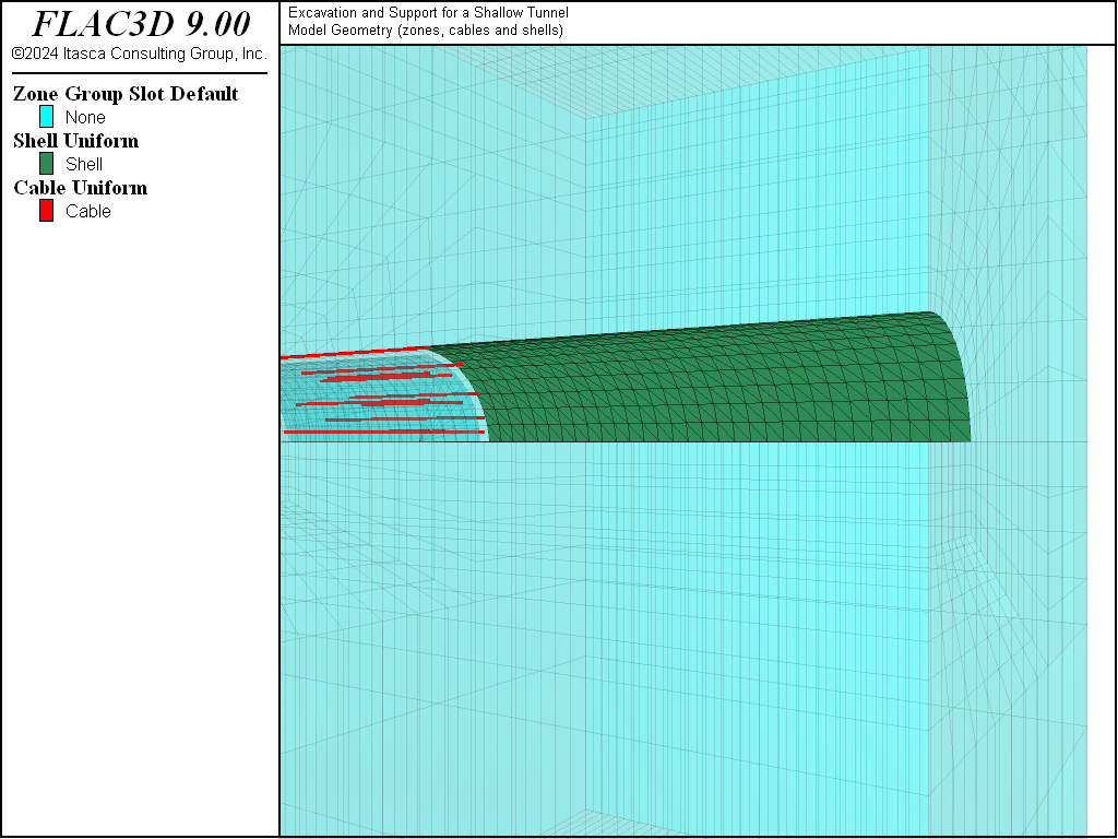
Figure 3: Structural elements (shells and cables) installed at construction step 10 (30 m excavation).
The lining components are modeled as elastic materials with the properties listed in Table 1 and Table 2.
Young’s modulus |
\(E\) |
10.5 GPa |
Poisson’s ratio |
\(ν\) |
0.25 |
Young’s modulus |
\(E\) |
31.4 GPa |
Poisson’s ratio |
\(ν\) |
0.25 |
Only one layer of shell structural elements is used in the analysis to represent both the pre-support concrete and shotcrete, while its thickness is varied accordingly. Note that the steel arch support is not explicitly modeled in this example. Its effect is combined with that of the shotcrete.
See Table 3 for properties of the cable material and the grout in the horizontal cable bolts installed at the tunnel face.
cable modulus |
45 GPa |
cable area |
1.57 × 10⁻³ m2 |
cable ultimate tensile capacity |
250 kN |
grout bond stiffness |
1.75 × 10⁷ N/m2 |
grout cohesive strength |
2.0 × 10⁵ N/m |
A combination of 9 m, 12 m, and 15 m length bolts are installed. The bolt installation process uses (alternately) three different bolt patterns.
The tunnel is constructed in two phases. First the upper, arched portion of the tunnel is excavated and supported. Then the lower portion of the tunnel is excavated and supported. In this example, only the first stage analysis is illustrated; the second stage construction would follow the same procedure as demonstrated here.
The excavation and support installation for the first phase are conducted incrementally, following the two-step sequence shown in Figure 1. A FISH function, excavate, defined in the file “tunnel-excavation.f3fis” is used to control the excavation and support installation processes. For each step, the excavation is advanced 3 m and the pre-support concrete shield, cable bolts, shotcrete, and thick concrete liner are installed at the specified distances from the tunnel face.
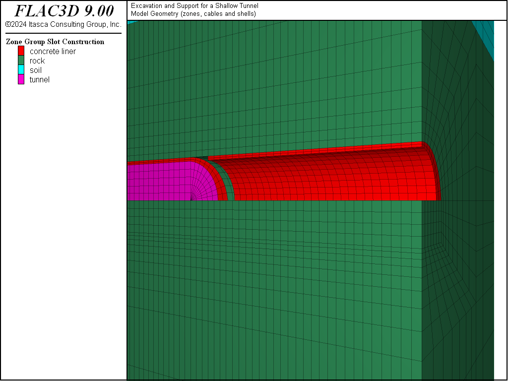
Figure 4: Groups of zones in the model.
In order to install a continuous lining with shell elements, the new shell element is given the same identification number as the existing shell element from the previous step. The new shell will then use the existing nodes at the connection with the existing shell. New shells have zero stresses initially.
The ground surface settlement and tunnel closure are monitored throughout the construction. These values are recorded at the end of each construction step and stored in tables.
A total of fifteen sequential excavation and support steps are performed. Each construction step is run to equilibrium, using a ratio-local of 1e-3 as the criteria.
Results
Selected results are shown in Figure 5 through Figure 11. Displacement histories at one point along the tunnel (30 m from the beginning of the tunnel) are plotted in Figure 5. Vertical displacement (at the ground surface and at the tunnel crown) and horizontal displacement (at the base of the tunnel sidewall) at the 30 m location are plotted against the 50 m excavation length.
The extent of the plasticity region around the tunnel after 30 m of excavation is shown in Figure 6. The different colors distinguish between shear and tensile failure. The suffix n (e.g., shear-n) indicates that the zone is now at active failure; the suffix p indicates that the zone has failed during a previous excavation step. The vertical displacement contours in the model after 30 m of excavation are shown in Figure 7.
The contours of stress resultant \(M_{xx}\) are shown in Figure 8 and Figure 9 after 15 m and 27 m excavations, respectively. The results are presented with respect to the local coordinate system with the \(x\)-axis coinciding with the global \(y\)-axis.
The axial forces in the cables are shown in Figure 10 and Figure 11 after 15 m and 27 m excavations, respectively.
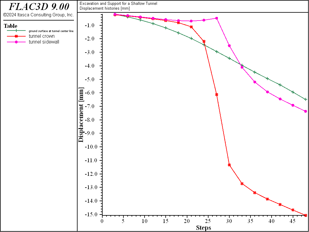
Figure 5: Displacement histories at 30 m position along the tunnel: table 1 = ground surface at x = 0; table 2 = tunnel crown; table 3 = tunnel sidewall.
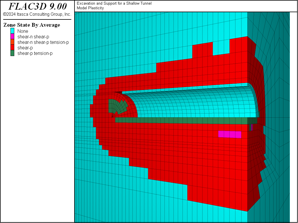
Figure 6: Plasticity region after 30 m of excavation.
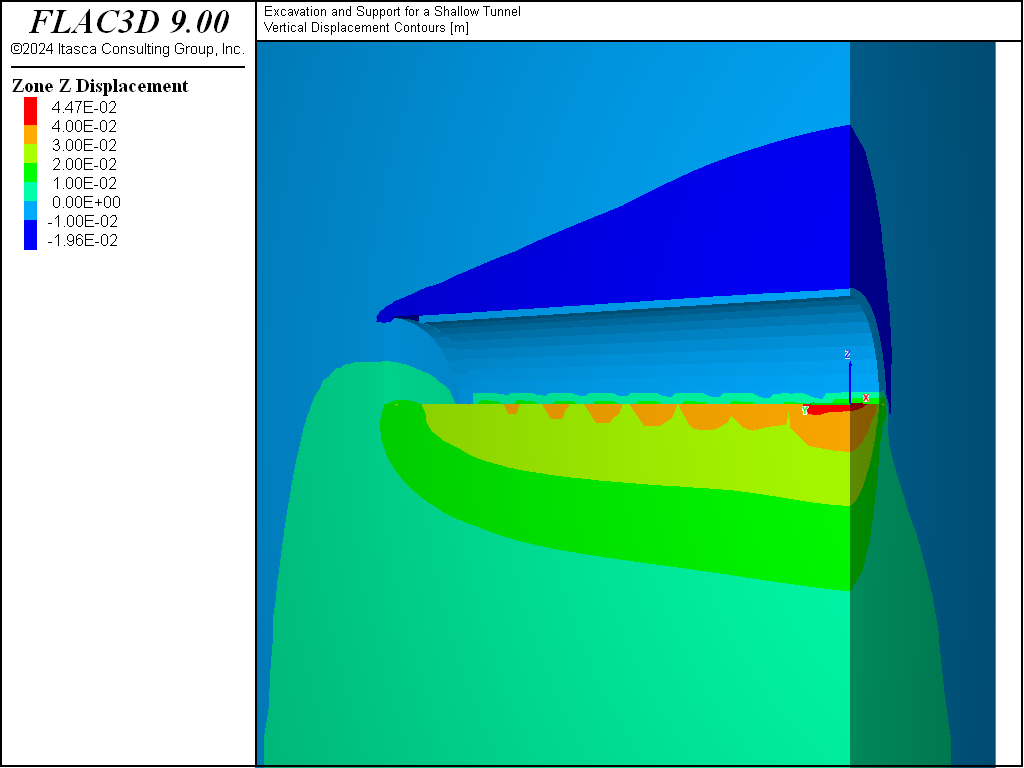
Figure 7: Vertical displacement contours after 30 m of excavation.
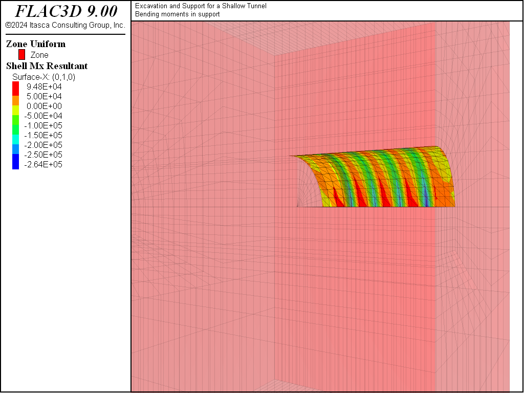
Figure 8: Bending moments in pre-support concrete and shotcrete after 15 m excavation (tunnel and liner zones hidden from view).
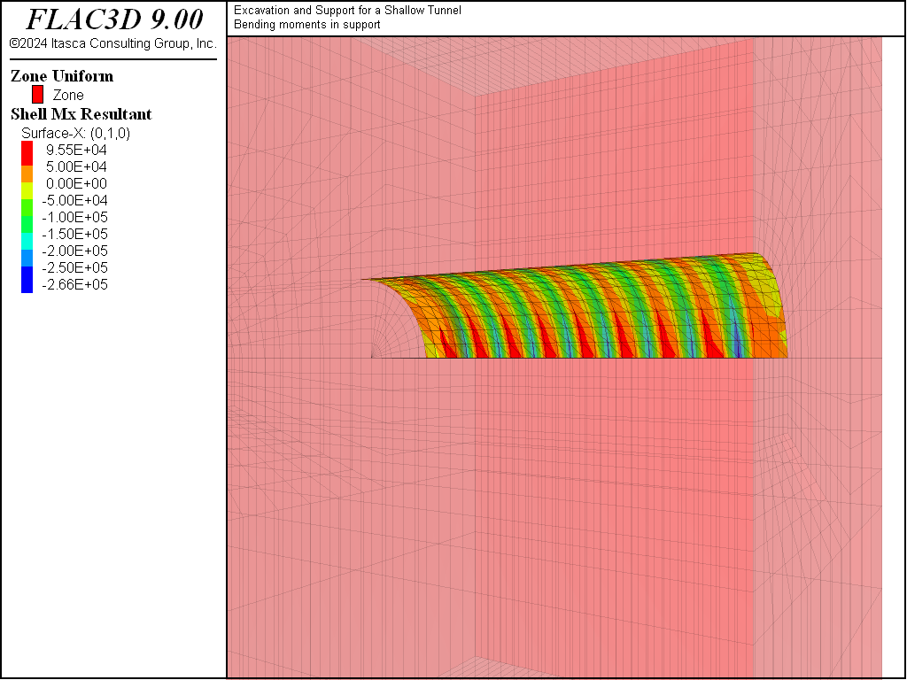
Figure 9: Bending moments in pre-support concrete and shotcrete after 27 m excavation (tunnel and liner zones hidden from view).
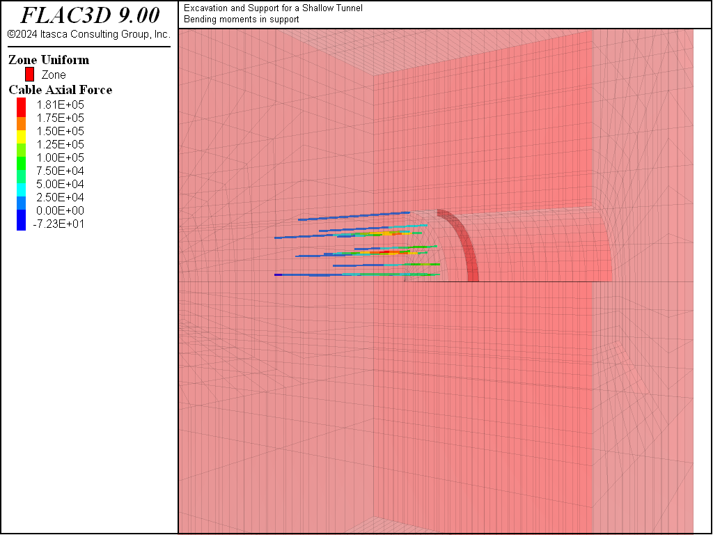
Figure 10: Axial forces in cables after 15 m excavation.
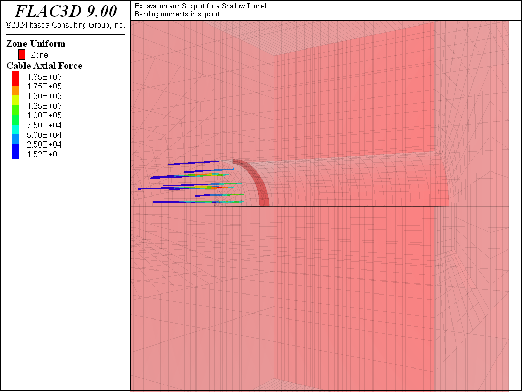
Figure 11: Axial forces in cables after 27 m excavation.
Data Files
ExcavationAndSupportOfShallowTunnel.dat
;-----------------------------------------------------
; ---- Excavation and Support for a Shallow Tunnel ---
;-----------------------------------------------------
model new
model large-strain off
fish automatic-create off
model title 'Excavation and Support for a Shallow Tunnel'
;generate grid using the Sketch tool
program call 'geometry' suppress
zone generate from-sketch
zone face skin ; Label model boundaries
; assign Mohr-Coulomb material model and properties
zone cmodel assign mohr-coulomb
zone property bulk 4e8  shear 1.5e8 friction 20 cohesion 50e3 ...
              tension 5e3 dilation 3 density 2200
zone property bulk 50e6 shear 18e6  friction 20 cohesion 25e3 ...
              tension 0 dilation 0 density 2200 range group 'soil'
; assign boundary conditions
zone face apply velocity-normal 0 range group 'East' or 'West'
zone face apply velocity-normal 0 range group 'North' or 'South'
zone face apply velocity-normal 0 range group 'Bottom'
; assign initial stress state
model gravity 10
zone initialize-stresses ratio 1.0 0.5
; monitor variables in model
model history mechanical ratio-local
zone history displacement-z position (0,0,5.)
zone history displacement-x position (7,0,0)
zone history displacement-z position (0,0,0)
zone history displacement-z position (0,0,35)
; Save initial geometry
model save 'geometry'
; Define cable patterns
program call 'tunnel-cable'
; install initial cables, as if in middle of sequence
structure cable import from-geometry 'cables' ...
                    segments 15 id 1 offset (0,-6,0) range group '1'
structure cable import from-geometry 'cables' ...
                    segments 15 id 2 offset (0,-3,0) range group '2'
structure cable import from-geometry 'cables' ...
                    segments 15 id 3 range group '3'
structure cable delete range position-y -100 0 ; Remove elements outside model
structure cable property young 45e9 cross-sectional-area 1.57e-3 ...
                      grout-perimeter 1.0 yield-tension 25e4 ...
                      grout-stiffness 17.5e6 grout-cohesion 20e4 ...
                      range id 1 3
; install pre-support concrete
structure shell create by-zone-face ...
                    internal reverse id 10 range group 'shell' position-y 0 1
structure shell cmodel assign elastic range id 10
structure shell property young 10.5e9 poisson 0.25 thickness 0.3 ...
                      density 2500 range id 10
; We define some points and tables to take data as we excavate
[global surface_gp = gp.near(0,30,35)]
[global crown_gp = gp.near(0,30,5.5)]
[global spring_gp = gp.near(7,30,0)]
table 'surface'  label 'ground surface at tunnel center line'
table 'crown'    label 'tunnel crown'
table 'sidewall' label 'tunnel sidewall'
; Solve to initial equilibrium
model solve convergence 1.0
; Save initial state of model
model save 'initial'
zone results model-mechanical on
; This FISH function actually performs the excavation and support sequence
program call 'tunnel-excavation'
[excavate]
model solve convergence 1
; Save final state
model save 'excavation'
tunnel-excavation.dat
;
; FISH function to control excavation and support sequence
;
fish define excavate
    ; Do 16 excavation steps
    loop global cut (1,16) ; Cut is global just so we can see where
                           ; we are in the FISH browser
        local y0 = 3*(cut-1) ; Start of cut
        local y1 = y0 + 3 ; 3m depth of cut
        local id = 10 ; ID number of shell
;       id = 10*(cut+1)  ; use if shells unconnected
        local idx = ((cut-1)%3) + 1 ; Index of cable pattern
        io.out(' EXCAVATION STEP ' + string(cut) + ' CABLE PATTERN ' ...
                                   + string(idx))
        ; Install pre support concrete, excavate, and delete cables
        ; in the excavated area.
        command
            ; install pre support concrete
            structure shell create by-zone-face internal reverse id [id] ...
                   range group 'shell' position-y [y0+1] [y1+1]
            structure shell cmodel assign elastic range position-y [y0+1] [y1+1]
            structure shell property young 10.5e9 poisson 0.25 thickness 0.3 ...
                                  density 2500 range position-y [y0+1] [y1+1]
            ; excavate next cut
            zone cmodel assign null ...
                 range group 'tunnel' or 'concrete liner' position-y [y0] [y1]
            ; delete-cables in the excavated area
            structure cable delete range position-y [y0] [y1]
            ; install new cables from pattern
            structure cable delete range id [idx]
            structure cable import from-geometry 'cables' segments 15 id ...
                         [idx] offset (0,[y1],0) range group [string(idx)]
            structure cable property young 45e9 cross-sectional-area 1.57e-3 ...
                                  grout-perimeter 1.0 yield-tension 25e4 ...
                                  grout-stiffness 17.5e6 grout-cohesion 20e4
            ; Increase shell thickness to represent shotcrete
            structure shell property young 10.5e9 poisson 0.25 thickness 0.5 ...
                                  density 2500 range position-y [y0-2] [y1-2]
        end_command
        if y1+15 > 51 then ; Delete cable elements outside model if necessary
            command
                structure cable delete range position-y 51 100
            end_command
        end_if
        ; Bring back concrete liner modeled as zones.
        if cut > 1 then
            command
                zone cmodel assign elastic ...
                     range group 'concrete liner' position-y [y0-3] [y1-3]
                zone property bulk 20.7e9 shear 12.6e9 ...
                     range group 'concrete liner' position-y [y0-3] [y1-3]
            end_command
        end_if
        ; Solve to equilibrium
        command
            model solve convergence 10
        end_command
        ; Store displacements in tables
        table('surface',3*cut) = gp.disp.z(surface_gp)
        table('crown',3*cut) = gp.disp.z(crown_gp)
        table('sidewall',3*cut) = gp.disp.z(spring_gp)
        ; Export results
        command
            model results export ['excavation-'+string(cut*3)]
        end_command
    end_loop
end
⇐ One-Dimensional Consolidation Considering Secondary Compression (FLAC3D) | Grid Generation for Intersecting Tunnels (FLAC3D) ⇒
| Was this helpful? ... | Itasca Software © 2024, Itasca | Updated: Apr 02, 2024 |
