
Simple Tutorial
Introduction
The model in the following image can be created in about two minutes in FLAC3D using the Extrusion pane. The following sequences show three different paths that will yield variations on the same model — each path illuminates different techniques and capabilities within the Extrusion pane and how, taken together, they provide a flexible and facile tool for mesh generation. It is assumed that the reader will work through the examples in order.
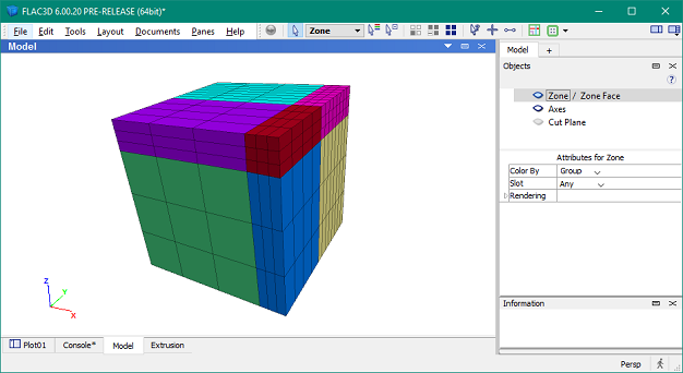
Figure 1: A FLAC3D grid created with the Extrusion pane
First Mesh
- Configure the interface so that only the Extrusion pane and the Control Panel are visible. To do so, choose Single from the Layout menu, then activate the Extrusion pane if necessary ().
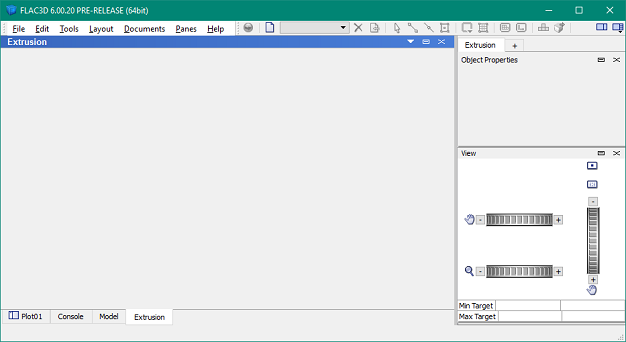
Figure 2: FLAC3D configured to work with the Extrusion pane
- Create a new extrusion set: Press the “New extrusion…” button (
 ). In the ensuing dialog, provide the name “first mesh”.
 - Draw a square: With the point-edge tool (
 ) active, you can click-move-click to draw each edge one at a time.
 - Block the square: Select the blocking tool (
 ), put the mouse cursor inside the square, then click. The new block will have an initial 3 x 3 zoning.
 - Split the block: With the blocking tool still active, place the mouse cursor in the center of the top-right zone and click. The model should now appear as seen here.
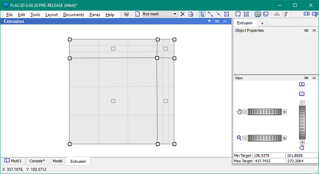
Figure 3: The “first mesh” extrusion set, blocked in the Construction view
- Switch to the extrusion view: Press the extrusion view button on the toolbar (
 ). Note that initial zoning has been applied - each light gray vertical line represents a zone.
 - Add a stage to the extrusion: Select the point-edge tool () and click the middle of the base line of the extrusion to place a new point there. This is effectively splitting blocks in the third dimension.
- Adjust zoning: Using the selection tool(
 ), click the segment forming the right side of the base line. Press Ctrl + → twice and enter “8” in the edit field of the “Zones” panel of the Popup Property Editor. Press Enter when finished to dismiss the Popup Property Editor. The model should appear similar to the image here.
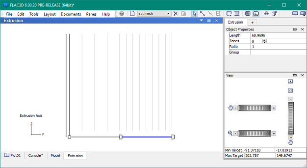
Figure 4: The “first mesh” extrusion set with zoning adjusted
- Extrude: Press the extrude button (
 ). The resulting mesh shown in the Model pane should look like the one shown in the image at the start of this section. (You may need to press Control+R to reset the view in the Model pane.)
Second Mesh
- Return to the Extrusion pane: Select on the main menu.
- Start a new extrusion set: Press the new button (). In the ensuing dialog, provide the name “second mesh”.
- Create the points of a square: Press spacebar to show the Popup Property Editor. Type the coordinates “0,0” and press Enter to add the first point. Repeat to create points at “0,100,” “100,0,” and “100,100.” If not all the points are visible when finished, press the reset view button (
 ) in the View control set in the Control Panel.
 - Connect the points: Pick the point-edge () tool. Move the mouse over one of the points. When it is highlighted cyan, click-move-click to join it to an adjacent point. Repeat this to draw the sides of the square.
- Block the square: Select the blocking tool (). Put the mouse cursor inside the square and click. Note the created block has an initial 3 x 3 zoning.
- Split the block: With the blocking tool still selected, click the top edge about midway through the top-right zone to create a vertical split. When this is complete, click again on the right edge, about midway through the uppermost zone to create a horizontal split. The model should now appear as seen here.
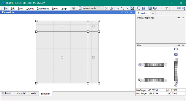
Figure 5: The “second mesh” extrusion set, blocked in the Construction view
- Modify the zoning: With the selection tool () active, click the center of the lower-left block. With the block selected, enter “4” in the “Zone Mult.” field of the control panel.
- Switch to extrusion view: Press the extrusion view button () on the toolbar. Observe that there is an initial depth to the model, supplied based on the extent of the model as drawn in the construction view.
- Adjust extrusion zoning: Select the point-edge tool and click the middle of the baseline of the extrusion to place a new point there. Right-click the edge forming the left half of the baseline to select the edge and show its properties in the Control Panel. Enter “1.5” in the “Ratio” field of the Control Panel, then enter “8” in the “Zones” field.
- Extrude: Press the extrude button () (delete any existing zones). The resulting mesh will have a similar shape to the first mesh, though the zoning of the model will be different (per the different zoning parameters supplied for the second mesh).
Third Mesh
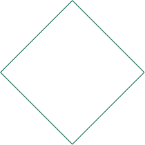
Figure 6: Example bitmap; copy this image (right-click and choose “Copy”) to paste and save this file for use in this example
- Acquire Bitmap: This iteration will illustrate including an image, starting with an imported bitmap like the one seen at right. To use the bitmap shown, right-click it and select “Copy.” Paste the bitmap image into a program that will allow you to save it in a FLAC3D-readable bitmap format (PNG, BMP, etc.).
- Go to the Extrusion pane: Select on the main menu.
- Start a new extrusion set: Press the new button () on the toolbar. Name this extrusion “third mesh”.
- Import bitmap: Press the import button (
 ) on the toolbar and locate the bitmap acquired in step 1. Select it and press the Open button to import the image.
 - Rotate bitmap: Double-click the bitmap. A successful double-click will cause the bitmap to be selected for resizing/repositioning. Double-click it again to activate rotation mode. When this mode is active, drag the bitmap until it has been rotated 45 degrees. When finished rotating, double-click the bitmap to deselect it.
- Trace the square: Pick the point-edge tool and click-move-click four connected segments that match the edges of the bitmap.
- Block the square: Select the blocking tool (). Put the cursor inside the square and click. Note the created block has an initial 3 x 3 zoning.
- Split the block: With the blocking tool still active, place the cursor in the center of the top-right zone and click. The model should now appear as seen in step 5. in First Mesh above.
- Autozone: Press the autozone button (
 ). In the Autozone dialog, select “model extent,” enter “12,” and press “OK.” The model should appear as seen here.
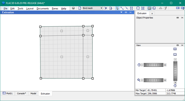
Figure 7: The “third mesh” extrusion set, blocked and zoned using the autozoning facility
- Switch to extrusion view: Press the extrusion view button () on the toolbar. Observe an initial extent of the model has been estimated. Press the autozone button (). In the Autozone dialog, select “model extent,” enter “12,” and press “OK.”
- Adjust the extent of the model: With the select tool already picked, select (click) the right (end) point on the base line. In the control panel, set the “Depth” property to 200.
- Adjust the zoning: Press the autozone button again. Select “Total number of zones” from the drop-down menu, and enter 40000. In the Extrusion view, the set will now appear similar to the image below. As the text in the dialog indicated, the “Total number of zones” setting affects the set in all directions. To verify, switch back to the Construction view and note how the zoning has changed.
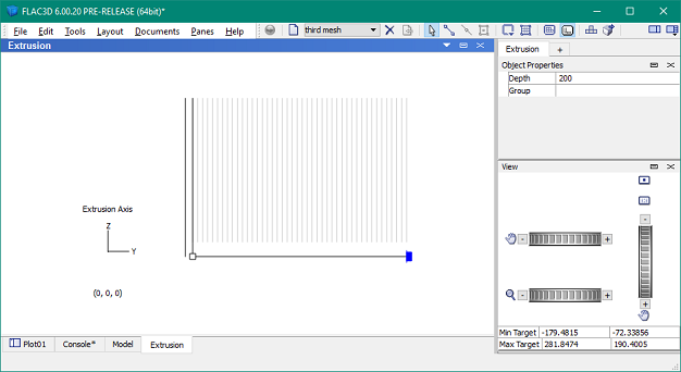
Figure 8: The “third mesh” extrusion set, autozoned in the Extrusion view
- Extrude: Return to the Extrusion view and press the extrude button (). The resulting mesh will have a similar shape to the first mesh, though the zoning of the model will be different (per the different zoning parameters supplied in the previous step).
| Was this helpful? ... | PFC 6.0 © 2019, Itasca | Updated: Nov 19, 2021 |