
Background Images / Geometric Data
Because background images in the construction view are intended to lie “under” the other objects (nodes, segments, blocks), selection and modification operations on them differ from the other objects.
An extrusion set accepts two types of background images: bitmaps (BMP, JPG, PNG, etc.) and geometric data sets (DXF, GEOM, STL). Either may be used as a guide to construct the extrusion. The difference is that a bitmap is, effectively, a picture, whereas a geometric data set contains the numeric information associated with the image and that data may be used in working with the image. This is described further below. Note a single extrusion set will accept one bitmap and one geometric data set only.
Import a Background Image
To use a background image in an extrusion, first it must be imported. Press the Import button ( ) on the toolbar. This will open a dialog that can be used to select the file to import. The accepted formats may be seen by using the “Files of Type” box in the dialog. When the “Open” button is pressed in the dialog, the image will be automatically placed in the construction view.
Select a Background Image
To select a background image, double-click anywhere within its limits using the select tool. When it is selected, it will appear with handle points at the corners and on the lateral midpoints, as shown here:
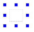
Figure 1: The handle points as they appear when an image is selected
An image may also be selected by right-clicking it and choosing the Select Background Image menu command.
Move a Background Image
Select the image per above, then drag from within the image (not on one of the handle points).
Resize a Background Image
Select the image per above, then drag a handle point. Aspect ratio is always maintained when resizing, regardless of which handle point is used in the operation. When the mouse is positioned over a handle point so that it may be used to resize, that point will be highlighted in cyan. The resize operation will take the point opposite the chosen handle point as an anchor (that is, the fixed point of reference) for the resize operation. See also Pin a Background Image below.
Pin a Background Image
A point of reference for resizing — a pin — may be set by first selecting the background image and then right-clicking it and selecting Set Pin from the context menu. This will change the mouse cursor to the pin ( ), which can be placed anywhere within the background image by clicking at the desired point. When setting the pin, it is useful to observe that the position of the cursor is reported in the status bar while it moves across the image. After clicking to set the pin, the image may be resized using that point as the anchor for resizing.
- Using the pin can be part of a process for precisely locating and sizing a bitmap for reference while building your model. For example, you may have an image that has two points that should be at known locations in your model. Call them Point A and Point B. You can:
- import the image
- press the spacebar to enter coordinates for Point A, which adds a point to the model at that location
- enter coordinates for Point B to add that point to your model
- double-click the image to select it
- move the image so that Point A in the image is at the same location as Point A in the model
- right-click the image and choose “Set Pin” from the context menu; the image must be selected for this command to appear in the context menu
- move the pin to Point A and left-click to set the pin at that location
- resize the image as needed using the handle points; with the image pinned, Point A of the image will stay in place while the rest of the image is resized; continue resizing the image until Point B in the image is at the same location as Point B in the model
- points A and B may be deleted from the model (or kept if needed) once resizing is complete.
When the image is de-selected, the pin is removed as well.
Rotate a Background Image
Select the image per above. Then repeat the double-click operation on the image. This will cause the handle points to be replaced with a rotation circle, as shown here:
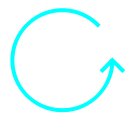
Figure 2: The rotation symbol indicates that dragging the image will cause it to be rotated in a direction that follows the motion of the mouse
While in this mode, press the mouse button within the image’s limits and drag to rotate the image. Rotation direction (clockwise, counter-clockwise) will mimic the direction of the mouse.
Cycling the Edit Modes
Repeatedly double-clicking the image will cycle through these three states: select for re-sizing/repositioning, select for rotation, and deselect. When selected for resizing, the right-click menu offers options for Next mode (go to rotation mode) or Exit Mode (deselect the image). In rotation mode, right-click offers Exit Mode (deselect the image) only.
Selection With Two Images in the Extrusion
An extrusion may contain one pixel-based (bitmap) image and one data-based (geometry) data set. In the event that these overlap and you double-click within an area of overlap, the order of edit states will be:
- select the bitmap for resizing/repositioning
- select the bitmap for rotation
- select the geometry for resizing/repositioning
- select the geometry for rotation
- de-select (remove selection)
Deselect an Image
Once an image is selected, it may be deselected in one of four ways: click anywhere outside the bounds of the bitmap rectangle (that is, anywhere outside the bitmap — including on any other object), double-click it while in rotation mode, select a different tool from the toolbar, or right-click the selected image and choose Exit Mode from the context menu. While a background image is selected you cannot select a different object with the selection tool, though clicking on one will cause the image to become deselected, at which point the clicked object may be selected.
Snap-To Behavior on Background Geometry
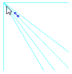
Figure 3: Putting the point-edge tool over any vertex of a geometric data set triggers a snap-to behavior that highlights all edges of the background image that meet at that vertex.
A geometric data set provides snap-to behavior when the point-edge tool is over it. When this tool is active and the mouse is over a point where two or more edges of the geometric data set intersect, the edges that join at the intersection will highlight to indicate that mouse-clicking at that point will cause a node to be placed at the vertex. If the mouse is over the middle of an edge, that edge will highlight to indicate that a mouse click will place a node on the edge. This behavior is not available on a pixel-based (bitmap) background image. Note, as seen in the image, the cursor does not have to be exactly over the vertex to trigger the snap-to behavior.
Holding the Shift key down while using the point-edge tool will suspend snap-to behavior. Holding the Control key down while adding an edge will cause the edge to snap to an angle even while snapping the end point to geometric data.
| Was this helpful? ... | PFC 6.0 © 2019, Itasca | Updated: Nov 19, 2021 |