
Simple Rigid Block Bonded-Block Modeling (BBM)
| Example Resources | |
|---|---|
| Data Files | Project: Open “SimpleBBM.prj”[1] in PFC |
Problem Statement
This example shows how to effectively use rigid blocks for simple Bonded-Block Modeling (BBM). The specimen created is shown below. This specimen is created using the rblock construct command. This command takes a geometry set and meshes it, creating a zero porosity packing of rigid blocks. The rigid blocks are then scaled so that they initially overlap. This is important for BBM modeling as, when rigid blocks are bonded, the computed contact location is only incrementally updated. In other words, the contact location does not
respond to changes in the overlap region. Instead, one can conceive of the contact location as the location
of an element of glue that is fixed to the surfaces of the rigid blocks until failure.
To dramatically increase computational performance, the rigid blocks are rounded with the rblock erode command. This command reduces the core shape and introduces rounding. This operation is important for rigid block modeling with zero porosity initial packings as the erosion removes many vertex-vertex and edge-edge contacts in the sense that they will be inactive. In fact, in this model with ~7700 rigid blocks there are ~13,000 face-face contacts between rigid blocks whereas there are more than 225,000 vertex-vertex and edge-edge contacts. These contacts contribute negligibly to test results but increase the computational time dramatically. In this model such contacts are inhibited with the contact inhibit command, meaning that they are skipped from all computations. If one were interested in very large strain where these contacts may be important, one could easily hook up a FISH function to the bond_break event and activate all or some subset of the contacts around the rigid blocks on each side of the contact.
The user must be aware that this procedure of requiring overlap for bonding results in the situation where if a contact model based on the Linear contact model is used the property lin_mode must be set to 1 so that normal forces are incrementally accumulated. Otherwise the initial overlap will result in initial contact forces that may lead to instability.
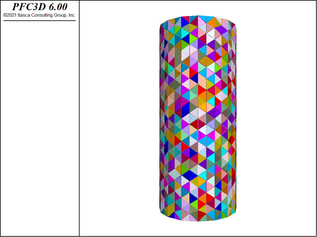
Figure 1: Initial specimen.
Simulation Results
A UCS and direct tension test are performed on the specimen. By specifying the initial velocities of the entire specimen and not just the platens, one can reduce any spurious oscillations in the stress-strain response. A FISH function is used to both compute the stress, strain and Young’s modulus and histories are kept of these quantities. The target material is a very brittle, hard rock with Young’s modulus 50 GPa, UCS strength ~ 110 MPa and tensile strength ~ 10 MPa. The Soft-Bond contact model is used without any softening for this simulation. With no softening this model is similar to the Linear Parallel Bond model in response with these notable exceptions: 1) the shear force is not reduced to 0 at shear failure but to the frictional sliding limit; 2) twisting resistance in 3D which is important for unbonded rigid blocks; 3) only one normal and shear stiffness is needed as opposed to separate parallel bond and linear stiffnesses.
The figures below demonstrate the UCS results run so that the residual strength is 80% of the peak. The desired peak value is achieved and the computed fragments show thorough failure of the specimen with both tensile and shear failures.
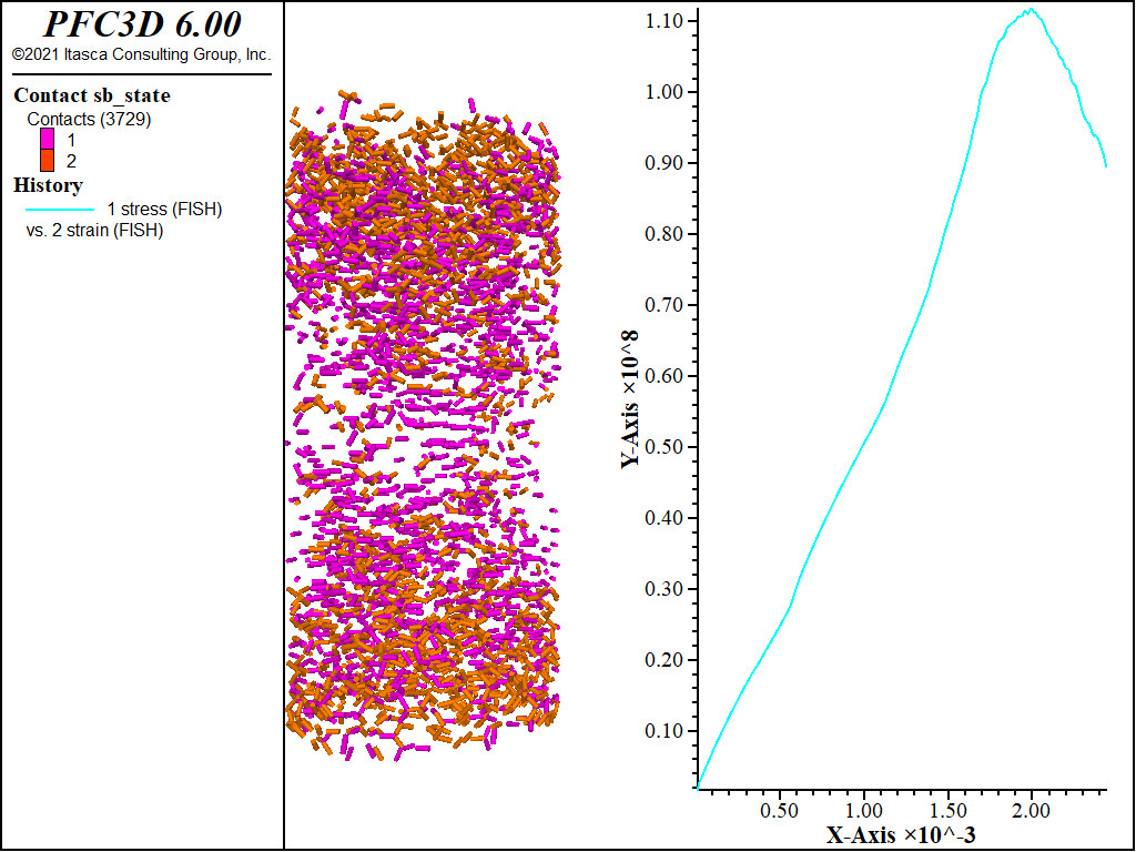
Figure 2: UCS results with failed bonds.
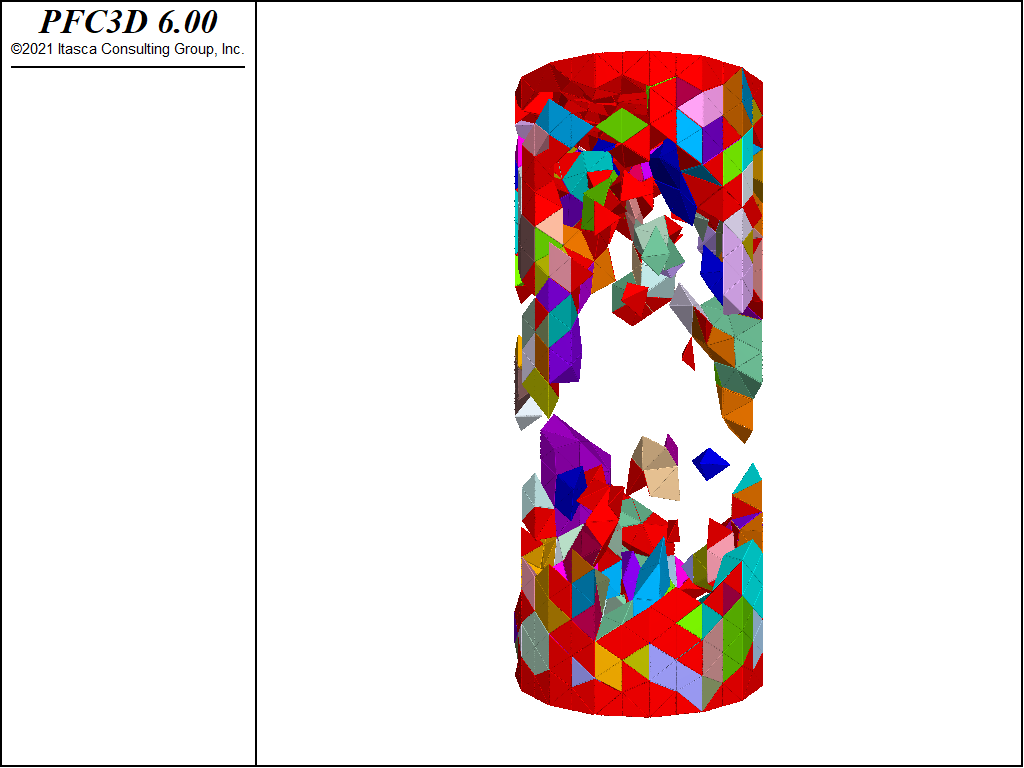
Figure 3: Fragments computed for the UCS test.
The figures below show the results of the direct tension test run so that the residual strength is 80% of the peak. Two distinct failure planes near the edges of the rigid blocks that are used as platens. The desired tensile strength is achieved.
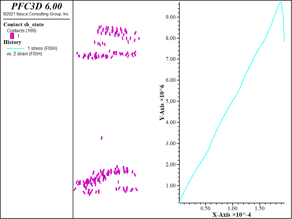
Figure 4: Direct tension results with failed bonds.
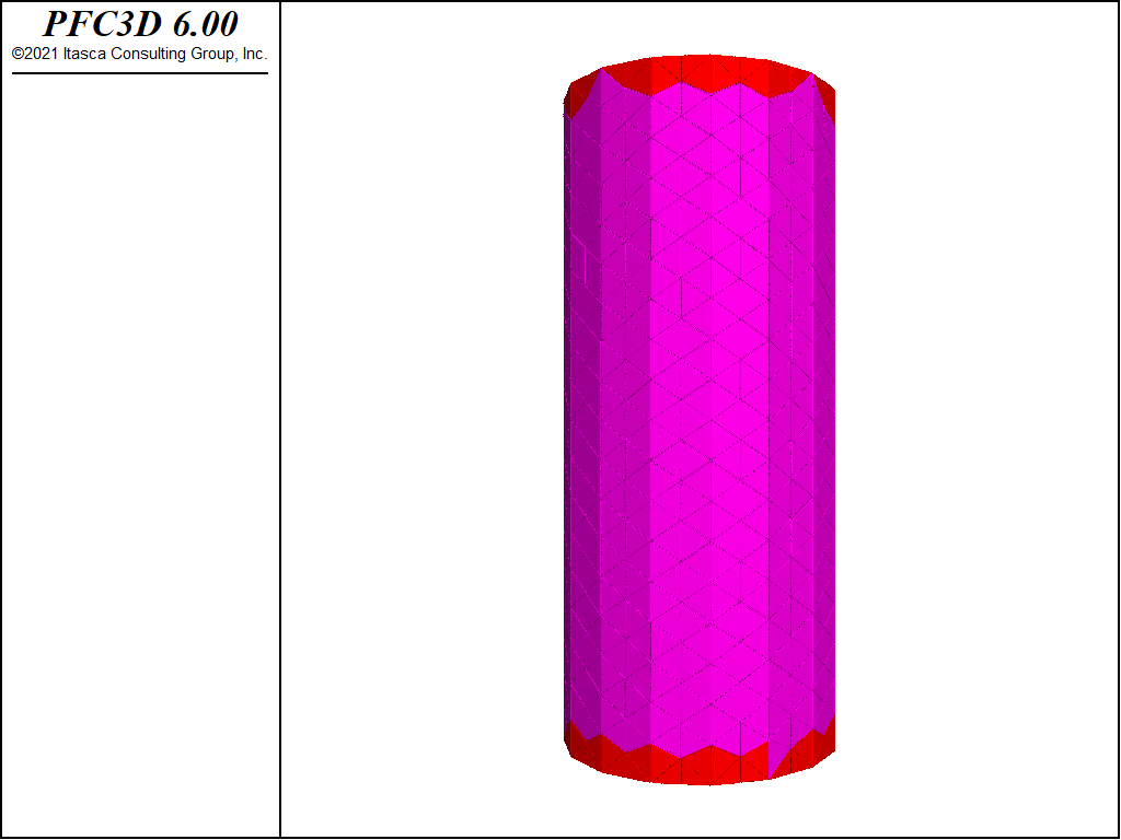
Figure 5: Fragments computed for the direct tension test.
| [1] | These files may be found in PFC under the “examples/simplebbm” folder in the Examples dialog ( on the menu). If this entry does not appear, please copy the application data to a new directory. (Use the menu commands . See the “Copy Application Data” section for details.) |
⇐ Data files for “Genesis and Testing of a Soft-Bonded Material”
Example |
Data Files for “SimpleBBM” Example ⇒
| Was this helpful? ... | PFC 6.0 © 2019, Itasca | Updated: Nov 19, 2021 |