
Ribbon Blender
| Example Resources | |
|---|---|
| Data Files | Project: Open “Blender_balls.p3prj”, “Blender_clumps.p3prj”, or “Blender_clusters.p3prj”[1] in PFC3D |
Problem Statement
Ribbon blenders are frequently used in manufacturing and industrial applications. The mixer has a central shaft with mixing blades angled in different ways. These look like ribbons of metal wrapped around the shaft. The geometry is able to move parts of the mixture in different directions at the same time, ensuring that all ingredients are blended.
The discrete element method is well-suited for this kind of application. A ribbon blender is modeled using PFC3D, and simulations are performed using three kinds of particles: balls, clumps, and clusters of balls (the latter allows simulation of particle breaking during mixing).
Balls Simulation
The geometry import command is used to import the geometry of the container, the shaft and the mixing blades. This command allows the direct use of CAD files (.dxf and .stl formats are supported) to include complex-shaped elements in the model that will interact with the particles. The file “importBlenderGeometry.p3dat” shows the use of the command.
Faceted walls are generated for each imported geometry, using the wall import from-geometry command. The blender structure issued from these operations is shown in Fig. 1.
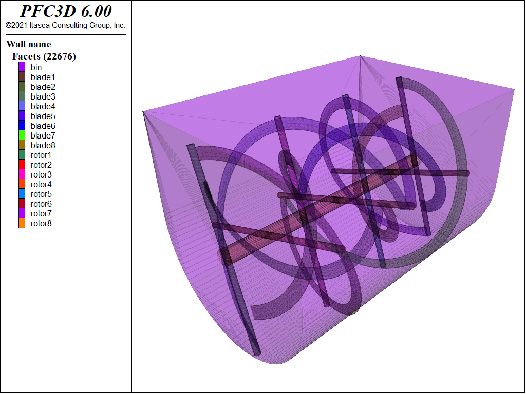
Figure 1: Modeling a ribbon blender.
An assembly of balls is then generated (see the ball distribute command) within the boundaries defined by the wall positions. Due to the complex geometry of the blender structure, particles are primarily generated within a box that exceeds the model boundaries in some zone. Then the position of each ball is revisited and the particle itself deleted whenever it is found to occupy a zone outside the model limits. This is done with the functions inBlender and inBody, which control whether each particle stays outside the model boundaries or whether it intersects the blender blades. The FISH function wall.inside and the range FISH commands are used to accomplish these operations. The former checks whether a particle falls within a wall or not; the latter allows automated detection of the particles to be deleted, according
to the criteria specified in the functions inBlender and inBody.
Finally, particles are allowed to settle inside the blender and the simulation is ready to start. A rotational velocity is defined for the walls and four sets of balls are grouped according to their initial positions in order to evaluate the mixing efficiency and effects during the simulation (see Fig. 2).
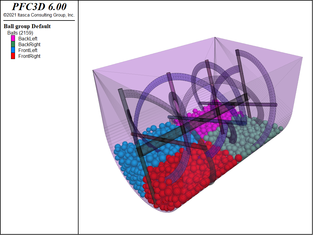
Figure 2: Modeling a ribbon blender to mix spherical particles.
All of the commands are listed in the file “BlenderBalls.p3dat”.
The mixing efficiency can be evaluated from a qualitative point of view. After a number of revolutions of the blades, we observe the result of mixing the four initial groups. A screenshot of the simulation after a few revolutions of the blades is shown in Fig. 3.
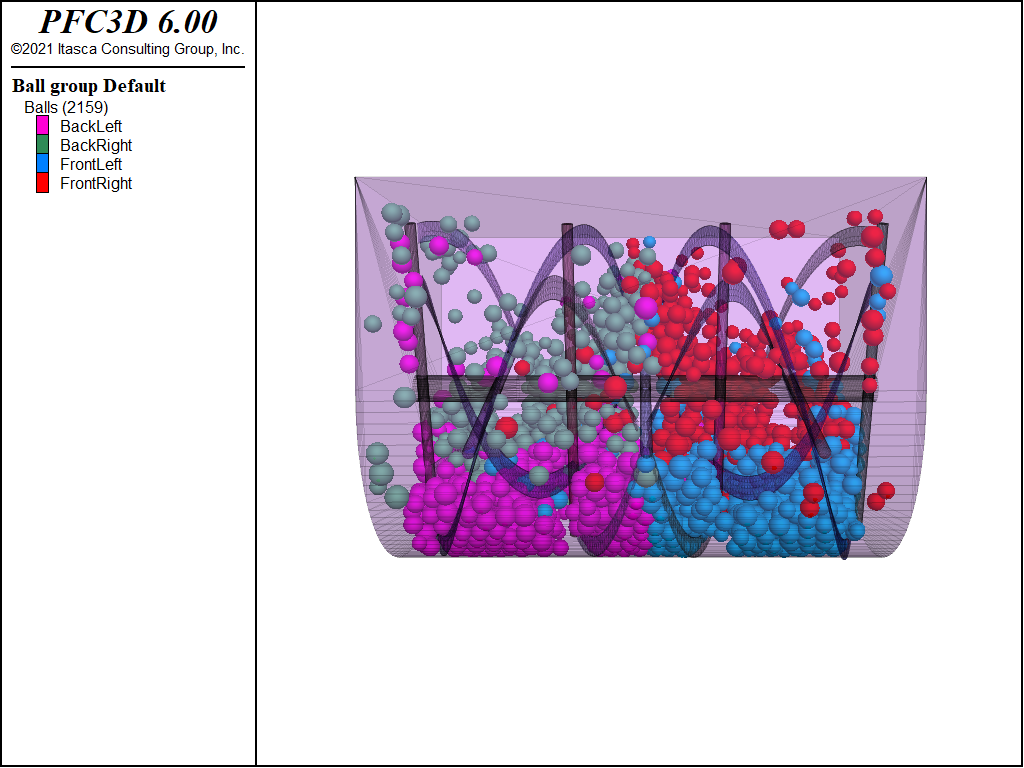
Figure 3: Side view of the blender after a few steps.
Clumps Simulation
Similar simulations can be done with nonspherical particles, using the clump logic. In particular, in this example, the geometry import command will be used to create a clump template. Thus, the “ellipsoid.stl” file is imported and used to define the clump template geometry, as it is shown in “BlenderClumps.p3dat”.
The geometry of the blender is imported using the same procedure that was used for the simulation with the spherical particles (see previous paragraph). A clump template is created, and an assembly of clumps is generated within the model boundaries. Clumps are made of pebbles that are rigidly connected, giving the final shape to the particle. Once the cloud of clumps has been created, the inBlender and inBody functions control whether any pebble stays outside of the model boundaries or whether they intersect the blender blades. In such a case, the entire clump is deleted (the range FISH command is used again). Finally, clumps settle inside the blender and the simulation is ready to start.
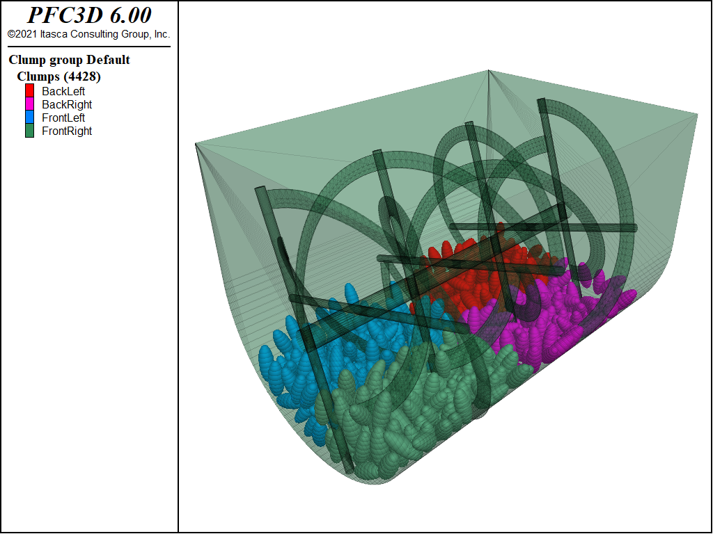
Figure 4: Modeling a ribbon blender to mix elliptic-shaped particles.
A screenshot of the simulation after a few revolutions of the blades is shown in Fig. 5.
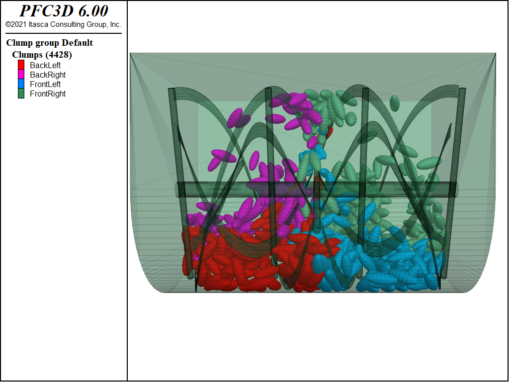
Figure 5: Side view of the blender after few steps.
Clusters Simulation
In order to simulate granulation, the clumps are replaced by clusters of balls. The pebbles are bonded together with parallel bonds. Such parallel bonds are characterized by user-defined tensile strength and cohesion, allowing for breakage during the simulation.
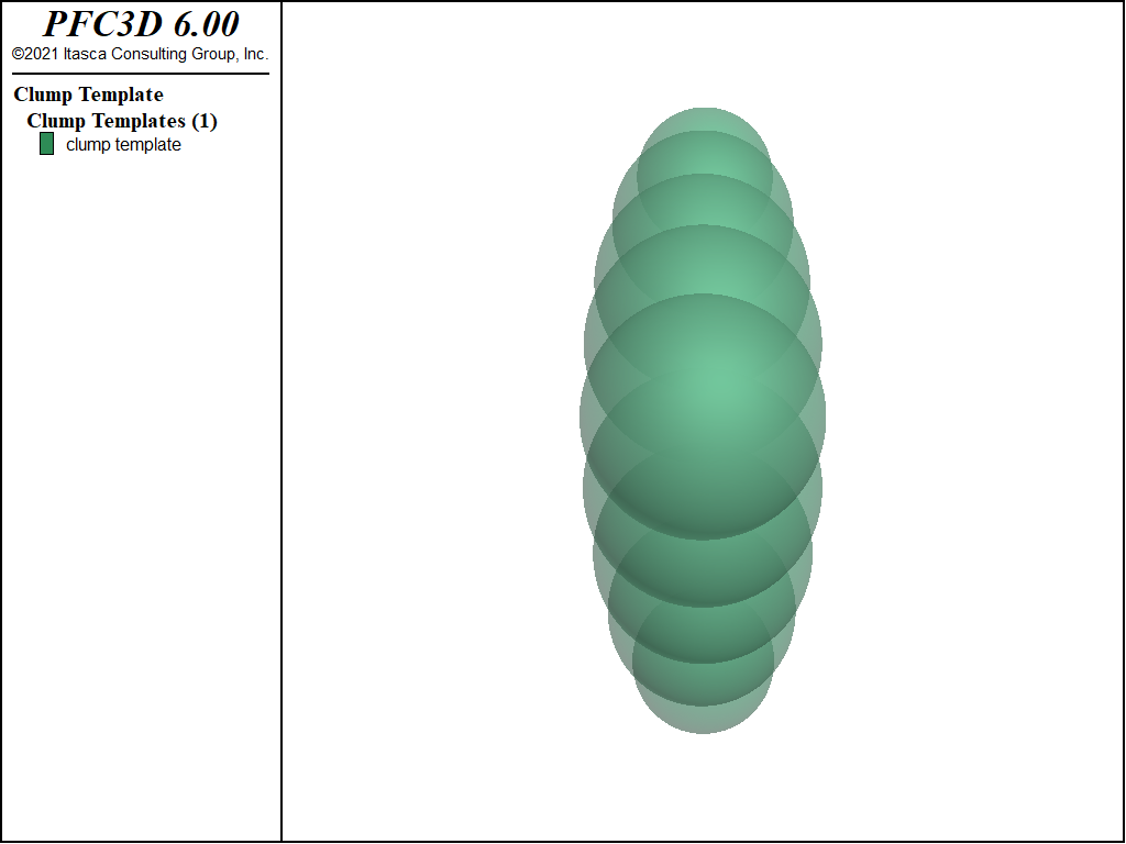
Figure 6: Cluster of balls.
Clumps are generated and allowed to settle, as shown in the previous section. Subsequently, the clumps are replaced by clusters of balls. Each operation is listed in “ClusterMakeCluster.p3dat”. The function replace goes through all of the existing clumps in the model and calls the function make_cluster, which contains the operations needed to substitute each pebble for a ball. Lists of balls comprising each cluster are created. These lists are then ordered to ensure that two consecutive balls in the list are neighbors in the cluster (see the order_clusters function). This allows one to easily install parallel bonds between neighboring balls, avoiding any accidental bonding of balls that overlap even if they are not neighbors, as shown in Fig. 6.
The function apply_bonds is invoked to install the parallel bonds whenever two balls are found to be part of the same cluster and are neighbors. Normal and shear stiffness of the bond, together with tensile and shear strength force, are defined. A linear model with friction is set at contacts between clusters. If a bond breaks during the simulation, the contact model between formerly bonded balls is switched to the linear type. A linearly increasing stiffness (see the lin_inc keyword of the linear model, in the “Linear Model Properties” section) is defined to avoid the sudden repulsive forces that could occur after breakage. A callback event bond_change is called whenever a bond breaks (see the “Linear Parallel Bond Model” section); the function restore_friction is called at the same moment, and the contact model is updated.
All of the operations for this new simulation are listed in “BlenderClusters.p3dat”.
Periodically during the simulation, the size_distribution function is called to compute the size distribution curve. This allows tracking the evolution of the system and breaking clusters into smaller particles. The size_distribution function is listed in “ClusterSizeDistribution.p3dat”.
It is useful to look at the evolution of the grain size distribution. The evolution of the grain size distribution curve is shown in Fig. 7. Note that the diameters plotted are the equivalent radius of the sphere that has the same volume as the total volume of the cluster.
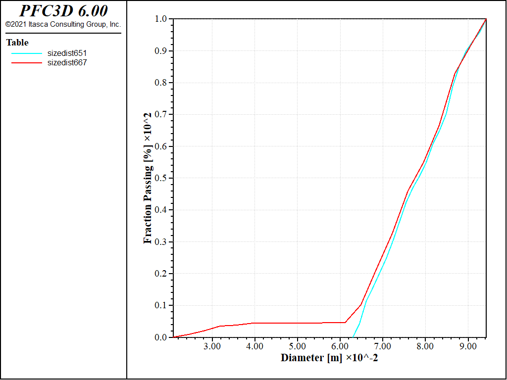
Figure 7: Cluster simulation. Evolution of the grain size distribution curve.
A screenshot of the simulation after a few revolutions of the blades is shown in Fig. 8. Particles are colored by their velocity. The strongest collisions and the breaking of particles seem to occur predominantly in the central zone of the blender.
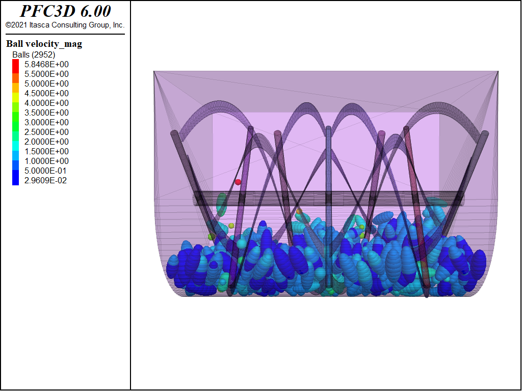
Figure 8: Cluster simulation, side view of the blender. Particles velocity.
It would be interesting to build a movie of such a simulation. Series of images can be easily generated using the ball results or clump results command. See the “Hopper Discharge” tutorial problem to see an example of its use.
Endnote
| [1] | These files may be found in PFC3D under the “example_applications/ribbonBlender” folder in the Examples dialog ( on the menu). If this entry does not appear, please copy the application data to a new directory. (Use the menu commands . See the -ref–dlg_copyappdata- section for details. [CS: commented out because UI material not present as of 9/25/17, therefore link is broken. Put back in when UI material is restored]) |
| Was this helpful? ... | PFC 6.0 © 2019, Itasca | Updated: Nov 19, 2021 |