
Rigid Block Model of Tunnel Excavation
| Example Resources | |
|---|---|
| Data Files | Project: Open “TunnelBBM.prj”[1] in PFC3D |
Problem Statement
This example simulates tunnel excavation in a deep, highly stressed environment, similar to the case study presented in [Garza-Cruz2014]. Stresses are installed in the initial, zero-porosity Bonded Block Model (BBM) consistent with a tunnel at 1200 m depth, where the lateral stresses are larger than the overburden stress. The Soft-Bond Model contact model provides both the elastic and failure response of the rock mass. The blocks are coupled with FLAC3D zones in order to create elastic boundaries away from the excavation region. After stress initialization, the tunnel is created by cutting the rigid blocks with fractures. The unbalanced forces on the cut blocks are computed, stored, and applied to the tunnel walls. These forces are subsequently relaxed to simulate tunnel advancement. Fragments are computed at various stages of relaxation. Bonds break initially in tension and shear near the tunnel surface but do not propagate. Shear failures occur at the tunnel corners and near the top of the tunnel, with tensile failures occurring primarily near the lateral walls. At higher levels of relaxation, one observes significant shear failures above and below the tunnel with interspersed tensile failures in all regions around the excavation.
Geometry Creation
The rblock construct command is used to create rigid blocks inside a parallelepiped domain. In order to remove regularity in the resulting tetrahedral packing, weights are placed at geometry nodes inside the volume to be meshed, and the internal keyword is given. The resulting tetrahedra form a zero-porosity representation of the rock mass, with specified maximum edge length, that conforms to the boundary of the parallelepiped. One could also create a Voronoi tessellation, using balls as seeds. This approach is not taken in this example.
The tunnel geometry is created as the composite of a cylinder and a parallelepiped box. As a result, some manipulation is necessary so that cuts only occur in the blocks at the edge of the tunnel. The geometry polygons are imported as fractures and used to cut the rigid blocks with the rblock cut command. The throughgoing keyword specifies that, should a fracture intersect any portion of a rigid block, the block is cut, while the intersects-box keyword specifies that only rigid blocks intersecting a box are considered for cutting. With these additional keywords the cuts can be performed without additional cuts occurring outside of the tunnel region. The assignment of a group name to the cut blocks allows one to define the intact walls of the tunnel in the rock mass for use later when applying support forces on the tunnel walls. The cut blocks at the tunnel periphery will be termed support blocks. Slivers are retained when cutting and will be removed as support pressure is applied. In this case the rblock contact-resolution command is used to specify that the stiffnesses are based on the contact area and not the enclosing sphere radii of the rblocks (the default behavior). The areas will are fixed using the contact method command with the area keyword.
For a zero-porosity model such as this one, one would expect that the contacts responsible for the elastic response would be located between the faces of adjacent tetrahedra, not located between tetrahedra edges or vertices. For non-bonded contacts, the contact location is defined as the centroid of the volume of overlap. Thus, in order for the face-face contacts to be identified and the contact locations to lie at the centroids of the face-face overlap regions, the rigid blocks are scaled (see the rblock scale command - note that the inertial properties are kept unchanged). Should the model be bonded in this state, there would be many edge-edge and vertex-vertex contacts that do not contribute to the elastic response and greatly slow the computation. To effectively remove these contacts during the simulation, two things happen: 1) the rigid blocks are rounded while keeping the face locations unchanged (see the rblock erode command) and 2) the rblock contact-resolution command is used to inhibit these contacts and to specify an interval for un-inhibiting the previously inhibited contacts. These steps of scaling, eroding, and inhibiting contacts between rigid blocks are vital to performant BBM simulations.
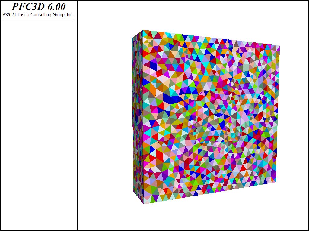
Figure 1: Initial configuration of the rigid blocks after cutting, scaling, and erosion.
Stress Initialization
Zones are created, densified, and attached in a region overlapping the rigid blocks. In order to set the zone stresses appropriately using the zone initialize-stresses overburden command, the zones must be contiguous. To accomplish this, the region overlapping the rigid blocks is initially elastic. Once the stresses in the zones have been initialized, the zones in the overlapping region are assigned the null constitutive model and the zone faces at the boundary of the elastic region are wrapped with walls with the wall-zone create command (see the figure below). The nulled zones are kept so that the zone stresses can be set again using the zone initialize-stresses overburden command, in order for the initial stress state to closely approach the target stress state. The contact forces are set using the rblock tractions command. These contact forces are not guaranteed to be exactly in equilibrium due to the variable contact orientations and varying number of contacts per rigid block or wall facet. The zone stresses are re-assigned to the target values and the model is equilibrated a few times to achieve a closer match to the target initial stress state. The figures below show the target xx-, yy-, and zz-stresses in the zones along with the final values
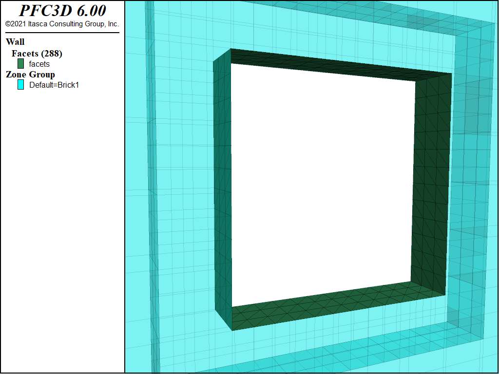
Figure 2: Zones with region wrapped by wall facets.
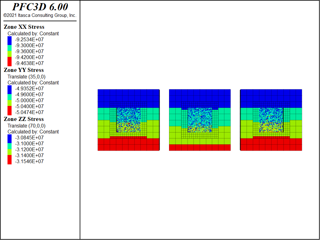
Figure 3: Initial xx-, yy-, and zz- stresses in the zones.
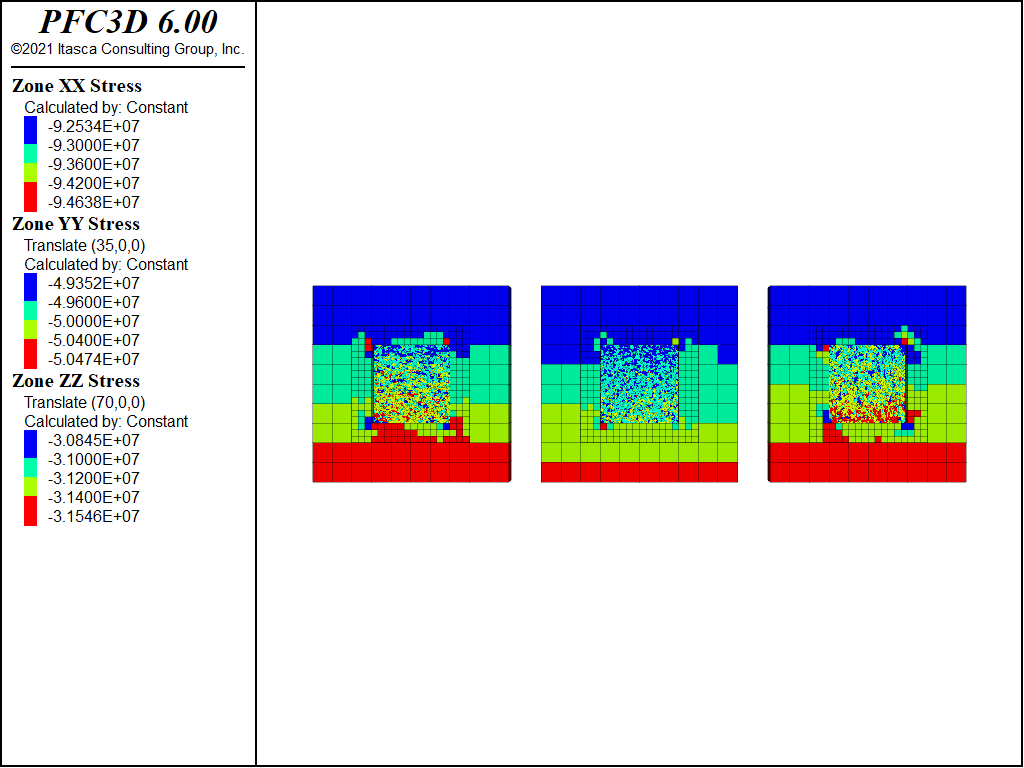
Figure 4: xx-, yy-, and zz- stresses in the zones equilibrated with blocks in the nulled region.
Tunnel Excavation
After the preceding steps the tunnel blocks are deleted, the support blocks are fixed, and the model is equilibrated. The support forces (i.e. the forces required to keep the tunnel from collapsing and near equilibrium) are computed as the negated out-of-balance forces on the support blocks. These support forces are stored as extra variables in each of the support blocks and applied to the support blocks. The support forces will be reduced later in the simulation. Normal distributions of tensile and shear strengths are specified for all rblock-rblock contacts. In an effort to keep the model in equilibrium while relaxing the support forces, a FISH halt is used that continues to reduce the support forces only when a target average ratio is obtained. In this example the target average ratio of 5e-4 might be larger than desired for certain situations.
Simulation Results
The following figures show the displacement magnitudes where the support forces are reduced to 30, 5, and 0 percent of their initial values. Note the continuity of displacements from the rigid blocks to the zones.
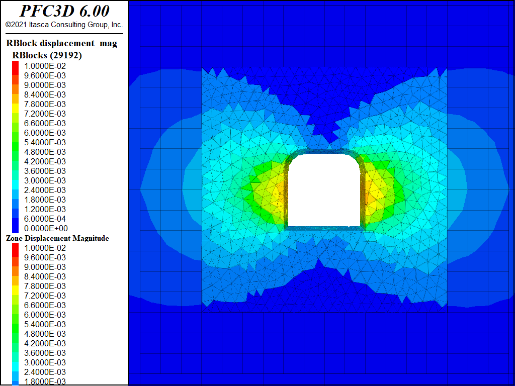
Figure 5: Displacement magnitude with support forces at 30 percent of their initial values.
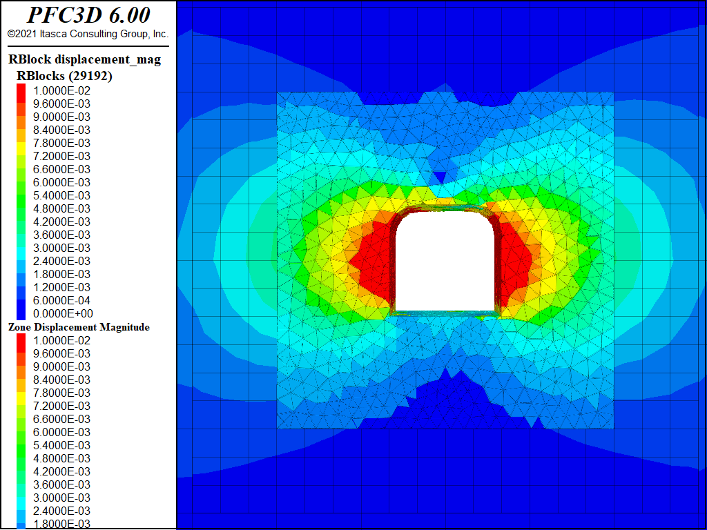
Figure 6: Displacement magnitude with support forces at 5 percent of their initial values.
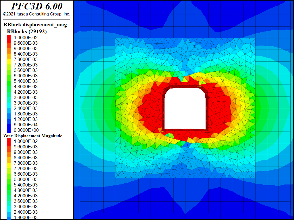
Figure 7: Displacement magnitude with no support forces.
The figures below show the shear and tensile crack evolutions where the support forces are reduced to 30, 5, and 0 percent of their initial values. The cracks are offset and the history of the current percentage of the initial support value is shown.
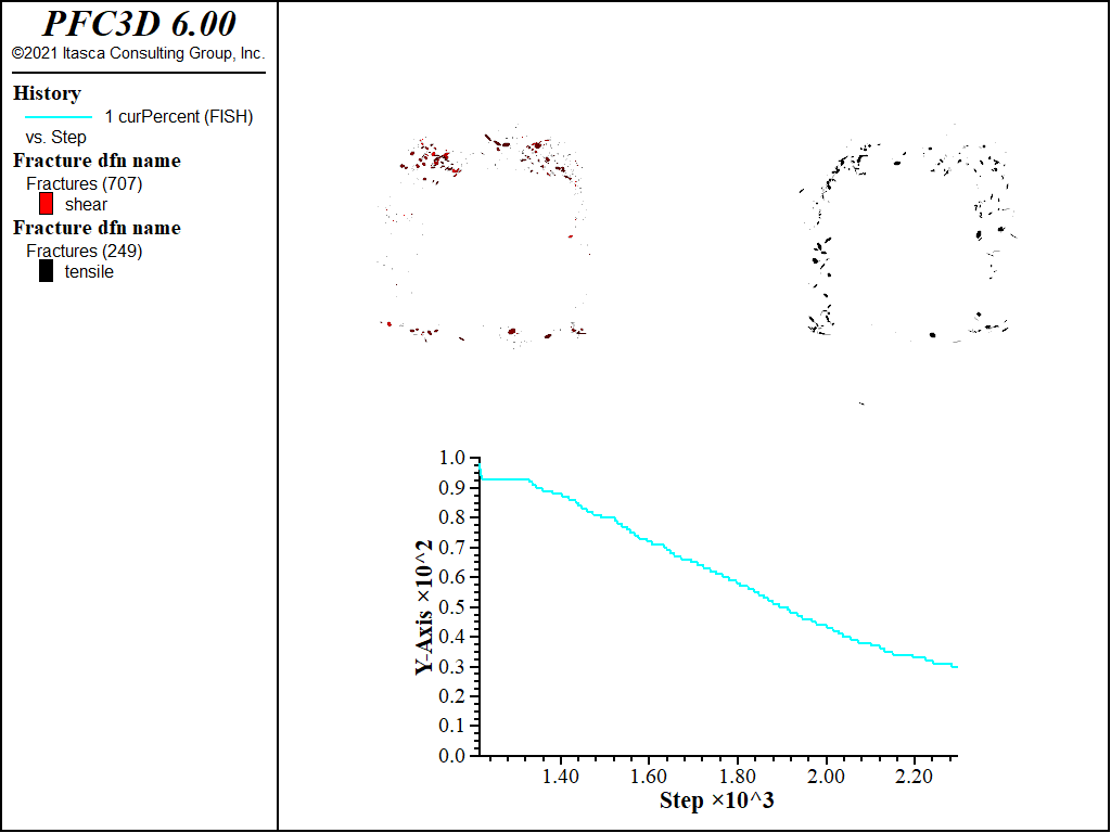
Figure 8: Shear (red) and tensile (black) cracks with support forces at 30 percent of their initial values.
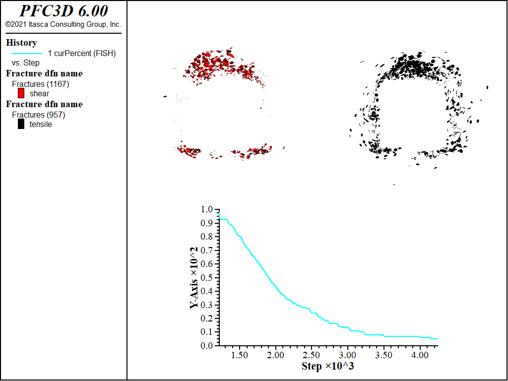
Figure 9: Shear (red) and tensile (black) cracks with support forces at 5 percent of their initial values.
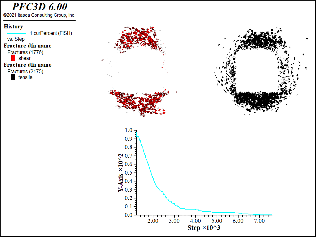
Figure 10: Shear (red) and tensile (black) cracks with no support forces.
Finally the figures below show the fragments where the support forces are reduced to 30, 5, and 0 percent of their initial values. Notice that the fragments develop first above and below the tunnel.
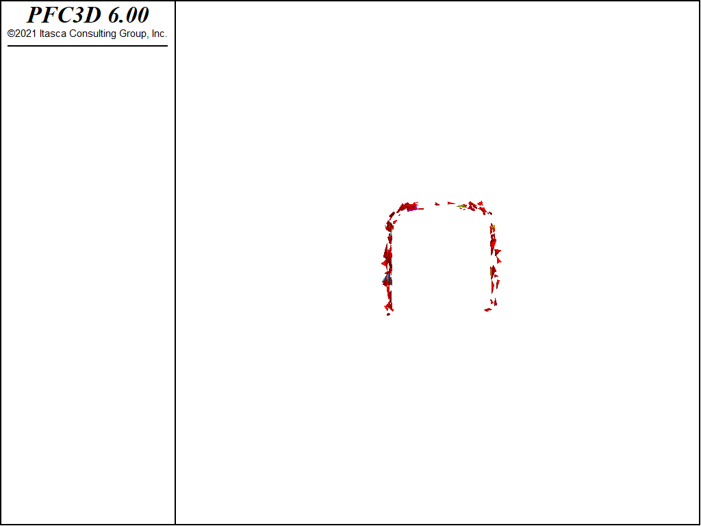
Figure 11: Fragments with support forces at 30 percent of their initial values.
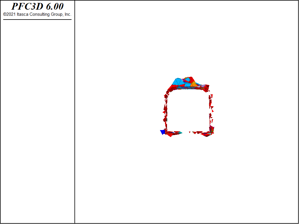
Figure 12: Fragments with support forces at 5 percent of their initial values.
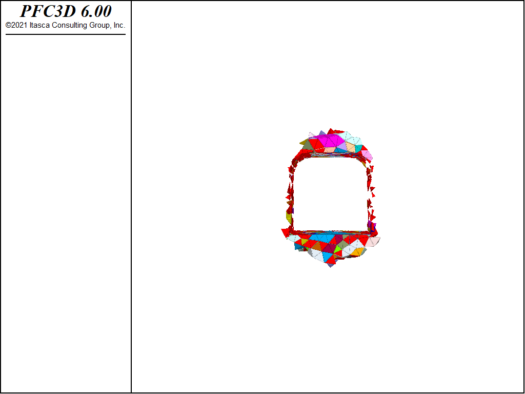
Figure 13: Fragments with no support forces.
References
| [Garza-Cruz2014] | Garza-Cruz, T. and Pierce, M., “A 3DEC Model for Heavily Veined Massive Rock Masses” in Proceedings of the 48th US Rock Mechanics Symposium, ARMA 14-7600, Minneapolis, MN, USA, 2014. |
| [1] | These files may be found in PFC3D under the “examples/tunnelbbm” folder in the Examples dialog ( on the menu). If this entry does not appear, please copy the application data to a new directory. (Use the menu commands . See the “Copy Application Data” section for details.) |
| Was this helpful? ... | PFC 6.0 © 2019, Itasca | Updated: Nov 19, 2021 |