
Highway Loading of an Arch Bridge
Problem Statement
Note
To view this project in 3DEC, use the menu command . Choose “3DEC/ ExampleApplications/ bridge” and select “bridge.prj” to load. The main data file used is shown at the end of this example. All data files are found in the project.
The assessment of the safety conditions of old masonry bridges is of particular interest because the bridges are often required to sustain heavier loads than in the past. This example illustrates the application of 3DEC to assess the ultimate load of a masonry arch bridge. A distinct element analysis is particularly well-suited to this type of problem because a significant portion of the deformation is accounted for by the relative motion between the masonry blocks that make up the bridge. For more details on this study, see the paper by Lemos (1995).
The ultimate capacity is required for the case of a masonry bridge that includes a semicircular arch vault and spandrel walls (see Figure 1). The dimensions of the bridge for this example are shown in the figure. Note that the fill material within the walls is not shown. Live loads representing the highway traffic are transmitted to the arch extrados through the spandrel walls. This example analysis is for an asymmetric loading that is applied by centering the resultant load on one of the walls. The load is increased in increments until failure occurs.
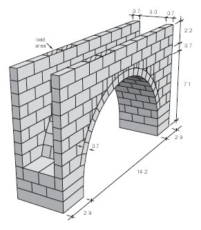
Figure 1: Masonry arch bridge — vault and spandrel walls.
Modeling Procedure
The 3DEC model for this example is shown in Figure 2. Some simplifications are made in order to reduce the computation time. For example, the fill material is represented by a dead load applied to the arch blocks. The spandrel walls are first generated by cutting two large blocks (which encompass the walls) with block cut joint-set command. Wall blocks adjacent to the arch are then created with block create prism command. The arch and foundation blocks are also created with block create prism command. The arch is composed of 75 blocks, which allows a reasonably accurate representation of failure mechanisms. The full model consists of 247 blocks. Figure 2 shows the full model, and Figure 3 shows the arch and foundation blocks. Blocks within the arch and foundation are assigned to group names \(arch1\), \(arch2\), and \(foundation\); blocks within the spandrel walls are assigned to region numbers \(wall1\), \(wall2\), and \(wall3\).
All blocks are made deformable with a coarse mesh. Blocks are assumed to remain elastic, and the only failure mechanisms involve joint sliding and opening. Crushing failure at the joints or under the loads was not considered.
The following properties are assumed for the blocks and joints:
| masonry block | |
| Young’s modulus | 50 GPa |
| Poisson’s ratio | 0.2 |
| masonry joint | |
| normal stiffness | 50 GPa/m |
| shear stiffness | 20 GPa/m |
| friction angle | 30° |
| cohesion | 0 |
| tensile strength | 0 |
The base of the lower abutment blocks is fixed from movement in all directions. The spandrel walls are unconstrained horizontally.
The model is first brought to equilibrium under gravity loading. Then the fill material within the walls is added as a dead load. Finally, the live load is represented as a force distributed over a selected area of the top of the spandrel wall. The resultant force of the live load is centered on one wall to provide an asymmetric loading. The initial live load corresponds to a force of 600 kN. This force is increased in increments of 600 kN until collapse occurs.
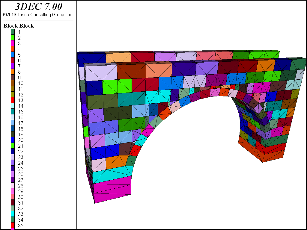
Figure 2: 3DEC model of masonry arch bridge.
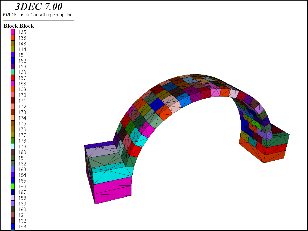
Figure 3: 3DEC model of masonry arch bridge — arch and foundation blocks only.
Results
The ultimate load of the bridge is identified by the \(y\)-displacement history monitored at a point on the arch beneath the applied load. The plot of \(y\)-displacement shown in Figure 4 indicates that continuous downward movement begins when the applied live load reaches 6000 kN.
Figure 5 shows the development of the collapse mechanism in the bridge at a later stage. In this advanced stage, the blocks directly under the load become detached.
In the analysis reported by Lemos (1995), the influence of the spandrel walls is shown to be significant. The spandrels provide both an increase in resistance to the failure load and a stiffening of the system.
Other 3DEC analyses of masonry wall bridges have also been conducted, including the evaluation of seismic effects. For example, see Lemos (1996 & 1997).
References
Lemos, J. V. “Assessment of the Ultimate Load of a Masonry Arch Using Discrete Elements,” in Computer Methods in Structural Masonry – 3, G. N. Pande and J. Middleton, eds. Books & Journals Int., pp. 294-302 (1995).
Lemos, J. V. “Discrete Element Modelling of Historical Structures,” in Proc. Int. Conf. New Technologies in Structural Engineering, S. P. Santos and A. M. Baptista, eds. LNEC, Lisbon, Vol. 2, pp. 1099-1106 (1996).
Lemos, J. V. “Discrete Element Modelling of the Seismic Behaviour of Stone Masonry Arches,” Computer Methods in Structural Masonry – 4, G. N. Pande, J. Middleton and B. Kralj, E&FN Spon, London, pp. 220-227 (1997).
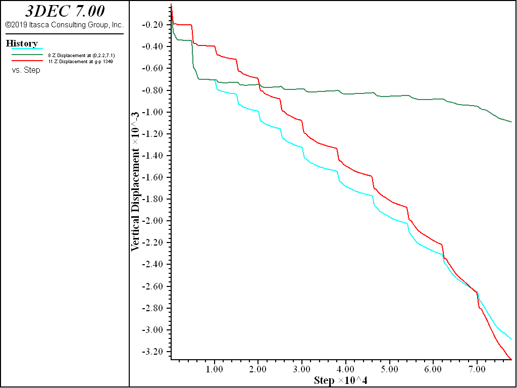
Figure 4: z-displacement at point (−3.8,6,−2.2) beneath applied load.
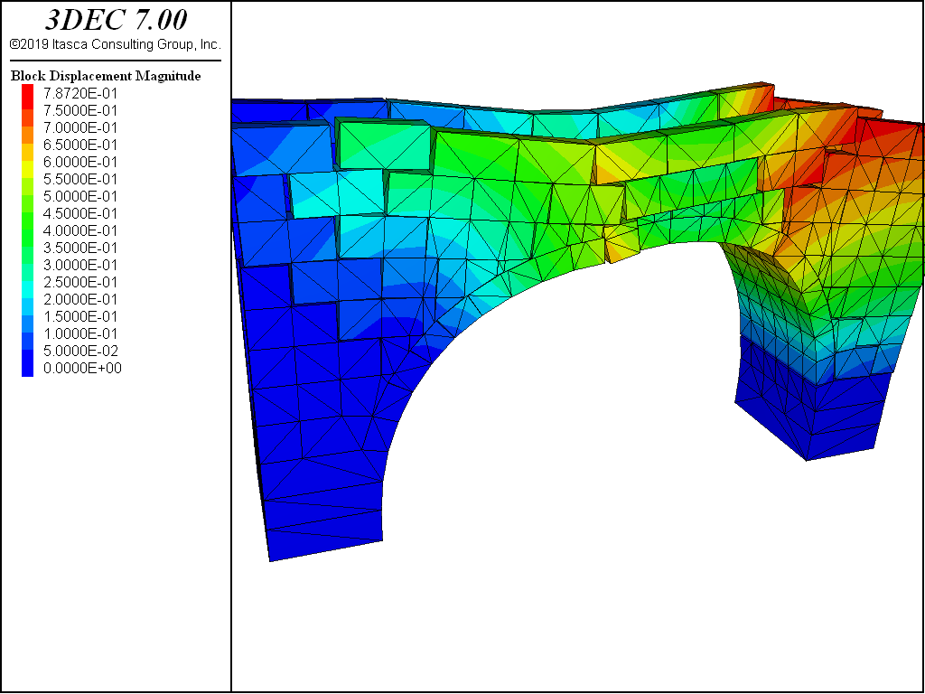
Figure 5: Failure of bridge.
Data File
bridge.dat
model new
model large-strain on

;  masonry arch bridge
block create brick -10 10 -2.2 -1.5 1.94 10
block create brick -10 10 1.5 2.2 1.94 10

; create spandrel wall blocks --------------
block cut joint-set ori 0 0 3
block cut joint-set ori 0 0 4
block cut joint-set ori 0 0 5
block cut joint-set ori 0 0 6
block cut joint-set ori 0 0 7
block cut joint-set ori 0 0 8
block cut joint-set ori 0 0 9
;
block group 'wall1' range position-z 0 3
block group 'wall2' range position-z 3 4
block group 'wall1' range position-z 4 5
block group 'wall2' range position-z 5 6
block group 'wall1' range position-z 6 7
block group 'wall2' range position-z 7 8
block group 'wall1' range position-z 8 9
block group 'wall2' range position-z 9 10
;
block hide range group 'wall1'
block cut joint-set dip 90 dip-direction 90 orig 0 0 0 spacing 2

block hide range group 'wall2'
block hide off range group 'wall1'
block cut joint-set dip 90 dip-direction 90 orig -1 0 0 spacing 2
block hide off
;
;
block delete range position-x -9 9 position-z 2 3
block delete range position-x -8 8 position-z 3 4
block delete range position-x -7 7 position-z 4 5
block delete range position-x -6 6 position-z 5 6
block delete range position-x -5 5 position-z 6 7
block delete range position-x -4 4 position-z 7 8
block delete range position-x -8 8 position-z 5 6
block delete range position-x -7 7 position-z 6 7

;
program call 'wall'
;
;

block hide range group 'wall3'
;
;  create arch and foundation blocks ---------------------------
program call 'arch'
;
block hide range group 'foundation'
;
block hide range group 'arch1'
block cut joint-set dip 90 dip-direction 0 ori 0 0 0

block cut joint-set dip 90 dip-direction 0 ori 0 -1.5 0

block cut joint-set dip 90 dip-direction 0 ori 0 1.5 0
;
block hide range group 'arch2'
block hide off range group 'arch1'
block cut joint-set dip 90 dip-direction 0 ori 0 -0.7 0

block cut joint-set dip 90 dip-direction 0 ori 0 0.7 0

;
block hide off
;
model save 'arch-blocks'

==============================================

;
block zone generate edgelength 10
;
;
block zone cmodel assign elastic
block zone property density 0.0027 bulk 20833 shear 22727

block contact jmodel assign mohr
block contact property stiffness-normal 50000 stiffness-shear 20000 friction 30
block contact material-table default property stiffness-normal 50000 ...
              stiffness-shear 20000 friction 30
;
model gravity 0 0 -10
block gridpoint apply velocity 0 0 0 range position-z -1.1 -0.9
;
model history mechanical unbalanced-maximum
model history damping
block history displacement-x position 0 -2.2 7.1
block history displacement-y position 0 -2.2 7.1
block history displacement-z position 0 -2.2 7.1
block history displacement-x position 0 2.2 7.1
block history displacement-y position 0 2.2 7.1
block history displacement-z position 0 2.2 7.1
block history displacement-x position -3.5 -2.2 6
block history displacement-y position -3.5 -2.2 6
block history displacement-z position -3.5 -2.2 6

history interval 100
;
model save 'arch-zoned'
;
; --- gravity ---
;
model solve
model save 'arch-gravity'
;
; -----------------------------------------------------------
; --- fill weight ---
;
block face apply stress 0 0 -0.22 0 0 0 gradient-z 0 0 0.022 0 0 0      ...
                 range position-x -7.57 7.57 cylinder end-1 0 -1.52 0   ...
                       end-2 0 1.52 0  radius 7.78 7.82
;
block face apply stress 0 0 -0.22 0 0 0 gradient-z 0 0 0.022 0 0 0 ...
                 range position-x -11 -7.52 position-y -1.52 1.52  ...
                       position-z 1.92 1.96
;
block face apply stress 0 0 -0.22 0 0 0 gradient-z 0 0 0.022 0 0 0  ...
                 range position-x 7.52 11 position-y -1.52 1.52     ...
                       position-z 1.92 1.96
;
model solve
model save 'arch-loaded'
;
; -----------------------------------------------------------
; --- load on one of the walls ---
;     increased until failure
;
;
fish def load1
  loop local i (1,4)
    fname = 'arch-'+string(i)
    command
      block face apply stress 0 0 -0.21428 0 0 0  ...
                       range position-x -6.1 -1.9 position-y -2.3 -1.4  ...
                             position-z 9.8 10.1
model cycle 5000
      model save [fname]
    end_command
  end_loop
end
[load1]
;
fish def load2
  loop local i (5,10)
    fname = 'arch-'+string(i)
    command
      block face apply stress 0 0 -0.21428 0 0 0 ...
                       range position-x -6.1 -1.9 position-y -2.3 -1.4  ...
                       position-z 9.8 10.1
model cycle 8000
      model save [fname]
    end_command
  end_loop
end
[load2]
;
model cyc 800000
model save 'arch-fail'
;
program return
| Was this helpful? ... | PFC © 2021, Itasca | Updated: Feb 25, 2024 |