
Development of Plastic Hinges in a Statically Loaded Beam
Problem Statement
Note
To view this project in FLAC3D, use the menu command . Choose “VerificationProblems/ PlasticHingesBeam” and select “PlasticHingesBeam.prj” to load. The main data files used are shown at the end of this example. The remaining data files can be found in the project.
A statically indeterminate beam of length \(2 l\) is loaded with a distributed load \(w\). This load corresponds to the self-weight of the beam. Assuming the beam can support a maximum bending moment, \(M^{pl}\) (after which a plastic hinge forms, and the section deforms indefinitely at constant load), the problem involves finding the maximum load, \(w^{max}\), that produces a kinematic mechanism and, consequently, the collapse of the system. The problem is illustrated in Figure 1.
This problem can be solved using the plastic theory of structures (see, for example, Riley and Zachary, 1989, pp. 581-586). According to this theory, the development of plastic hinges is dictated by the occurrence of maximum bending moments.
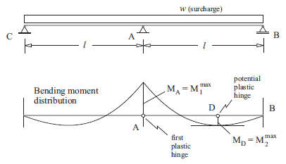
Figure 1: Bending moment distribution in a statically indeterminate continuous beam
The lower part of Figure 1 displays the bending moment distribution for the continuous beam assuming elastic behavior. The maximum moment occurs at the position \(A\), indicated as \(M_A=M_1^{max}\) in the figure. A second maximum moment occurs at point \(D\) and is indicated as \(M_D=M_2^{max}\). (Note that, for the given, symmetric, problem geometry, there is another point \(D\)—not indicated in the figure—between points \(C\) and \(A\).)
Consider a gradually increasing surcharge, \(w\), acting on the beam. If the maximum plastic moment that the beam supports is \(M^{pl}\), the first plastic hinge will develop at the point where \(M^{pl}\) is reached first (i.e., at point \(A\)). After the first hinge has formed, the problem is still stable. The system behaves as two separate beams with a constant bending moment \(M^{pl}\) at point \(A\). Collapse of the system will occur when a second hinge develops (i.e., at point \(D\) where the second maximum bending moment occurs). This is because a second hinge at position \(D\) creates a kinematic mechanism that allows the roller at point \(B\) to freely move toward the right.
The formation of hinges can be modeled with FLAC3D. The problem illustrated in Figure 1 provides a test of the plastic-hinge logic implemented in the code.
The problem conditions for this test are
| length | \(l\) = 10 m |
| height | \(h\) = 1 m |
| plastic moment | \(M^{pl}\) = 50 MN-m |
| Young’s modulus | \(E\) = 210 GPa |
Note that the properties associated with the deformability of the beam (the height, \(h\), and Young’s modulus, \(E\)) are not relevant in this problem but are needed as input for the FLAC3D model.
Closed-Form Solution
The location of the point \(D\) in Figure 1, where the second plastic hinge develops, can be found from simple beam theory analysis.
Consider the simply supported beam shown in Figure 2. This represents the situation after the first plastic hinge has developed at the midpoint in Figure 1. The bending moment at point \(A\) is constant and equal to \(M^{pl}\).
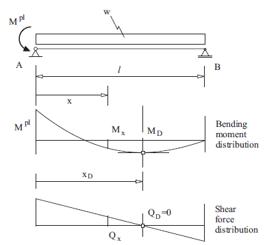
Figure 2: Bending moment and shear force distribution after plastic hinge has developed at point A.
Figure 2 also illustrates the distribution of bending moments \(M(x)\) and shear force \(Q(x)\) along the right half of the beam. The objective, then, is to find the coordinate, \(x_D\), of the maximum bending moment where the second plastic hinge that produces collapse will develop.
The reaction force at point \(B\) is obtained from the condition of equilibrium of moments at point \(A\), i.e.,
The distribution of shear force, \(Q(x)\), is given by
The distribution of bending moment, \(M(x)\), is given by
The coordinate \(x_D\) can be found from the preceding expressions and the condition \(Q(x_D)=0\)
The maximum surcharge \(w^{max}\) is found from the condition \(M(x) = M^{pl}\) at \(x=x_D\)
By application of these equations, the position of the second plastic hinge, \(x_D\), and the maximum load, \(w^{max}\), can be determined. The results are
FLAC3D Model
This problem is solved using the two different approaches to determine plastic hinges in FLAC3D (see Beam-Type Properties). The first approach involves assigning a limiting plastic moment at structural nodes, and the second requires creating double nodes at each node location and assigning a deformable link to connect each double node.
Plastic hinge formation by limiting plastic moment — For this approach, we assign a limiting plastic moment for all structural nodes using the structure beam property plastic-moment command. The right
half of the beam is discretized into 20 elements of length 0.5 m each (see Figure 3). The beam contains 21 nodes, and each node has a limiting plastic moment of 50 MN-m.

Figure 3: FLAC3D model of the beam in Figure 1.
Plastic hinge formation by double-node approach — For the second approach, we define double nodes at all structural nodes that have the potential for a plastic hinge to develop. The right half of the beam is
discretized into 20 elements of length 0.5 m each. Each element is defined by two nodes (by using the separated keyword during the structure beam create command); thus, the beam has 40 nodes.
The nodes of adjacent elements are linked together using the structure node join command to allow the potential for the formation of a plastic hinge.
There are 19 links (i.e., all nodes except the extreme nodes in Figure 3 are linked; each pair of nodes defines a link). The limiting plastic moment is assigned to the links by first changing the link conditions with the structure link attach command, and then prescribing deformable link properties for the \(y\)-rotation via the structure link property command. The plastic moment is assigned to this command with the yield-compression and yield-tension keywords.
Applying a uniform surcharge in both approaches — The effect of the uniform surcharge \(w\) (see Figure 2) is represented by forces that are applied to the nodes. This is done by applying a distributed load with the structure beam apply command. The surcharge load, \(w\), is assigned via the FISH variable load, which is increased from 5.5 to 6.6 in 0.05 increments. The maximum surcharge is determined by finding the level of loading that does not reach equilibrium.
The equilibrium of the system is found by issuing a model solve command. Cycling is continued until the local unbalanced force ratio falls below the default limiting value of 1 × 10⁻⁵ or 100,000 steps are taken. If this step limit is achieved without reaching the limiting ratio, the system is assumed to be unstable.
The function find�_critical�_load saves each stage of the loading process and displays the status of the model being solved on the screen (i.e., whether equilibrium is reached for the current level of surcharge). This file is printed to determine the load, \(w^{max}\), that produces collapse of the beam.
Results and Discussion
The output indicates that the system does not reach equilibrium for a load \(w^{max}\) = 5.85 MN/m. The last stable case in the preceding listing is for a load of 5.80 MN/m. These results bound the value computed with the analytical solution.
The distribution of bending moments and shear forces before collapse can be obtained from the file “plasticmoment_580.f3sav”—see Figure 4 and Figure 5.
The location of the failed hinge can be seen by plotting the link yield state indicators in the \(y\)-rotation degree-of-freedom, as seen in Figure Figure #plastichingesbeam-yieldstate. Note that only one of each pair of nodes has a link, so the side of the element connected to that node will display the “No Link” state. The plot indicates that the plastic hinge developes at link 12. Each element has a length 0.5 m; thus, the failed link is located at a distance of 6 m. This is within reasonable agreement with the analytical solution in the closed form solution that predicts a value of \(x_D\) = 5.86 m. The plastic hinge can also be observed by the plot of magnified geometry and displacement, as shown in Figure 6 for the limiting plastic moment approach.
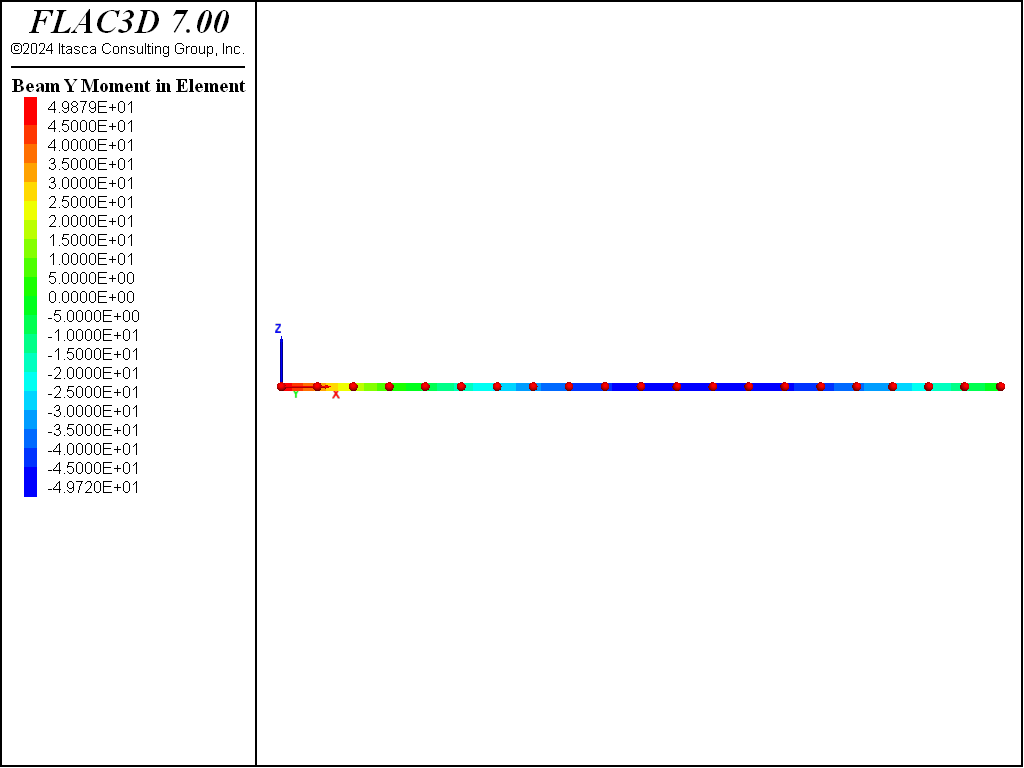
Figure 4: Distribution of bending moments before failure for double-node approach (w = 5.8 MN/m).
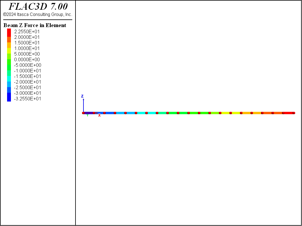
Figure 5: Distribution of shear forces before failure for double-node approach (w = 5.8 MN/m).
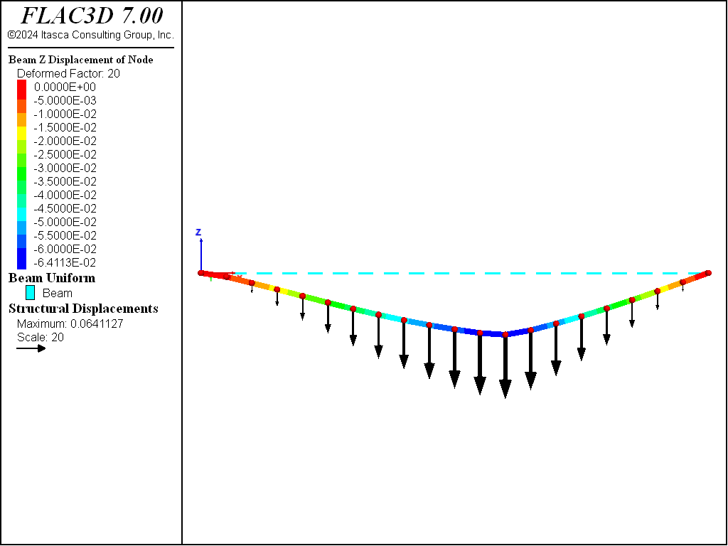
Figure 6: Magnified beam geometry and displacement vectors for limiting plastic moment approach.
Reference
Riley, W. F. and L. Zachary. Introduction to Mechanics of Materials. New York: John Wiley & Sons Inc. (1989).
Data Files
plastic-moment.dat
model new
model large-strain off
fish automatic-create off
;
struct beam create by-line (0,0,0) (10,0,0) segments 20
; Tag nodes with names
struct node group 'Begin'  range position-x 0
struct node group 'End'    range position-x 10
; beam properties
struct beam property young 210e3 poisson 0.3
struct beam property cross-sectional-area 1.0 moi-y 0.083 moi-z 0.083 ...
                     moi-polar 1.25e-4 plastic-moment 50
; fix b.c. for external nodes
struct node fix velocity rotation-x rotation-z range group 'Begin'
struct node fix velocity-y velocity-z rotation-x rotation-z range group 'End'
; apply bending moment
struct node apply moment (0,-50,0) range group 'Begin'
; take a history
model history mechanical ratio-local
;
fish define find_critical_load
    loop global load (5.5,6.5,0.05) ; Load is global just so you can see
                                    ; progress in the FISH browser
        local starting_cycles = mech.step
        global filename = 'plasticmoment_' + string(load*100)
        command
            history purge
            struct beam apply (0,[-load])
model solve ratio-local 1e-5 or cycles 100000
            model save [filename]
        end_command
        local solve_cycles = mech.step - starting_cycles
        local line = 'STABLE'
        if solve_cycles >= 100000
            line = 'UNSTABLE (maximum steps reached)...'
        else if load > 6.5
            line = 'STABLE and LAST'
        end_if
        io.out(line)
        if line # 'STABLE'
            exit loop
        end_if
    end_loop
end
[find_critical_load]
model save 'plasticmoment_final'
program return
double-node.dat
model new
model large-strain off
fish automatic-create off
; Created the beam using the separated keyword so elements do not share nodes
struct beam create by-line (0,0,0) (10,0,0) segments 20 distinct
; Tag nodes with names
struct node group 'Begin'  range position-x 0
struct node group 'End'    range position-x 10
; beam properties
struct beam property young 210e3 poisson 0.3
struct beam property cross-sectional-area 1.0 moi-y 0.083 moi-z 0.083 ...
                     moi-polar 1.25e-4
; Boundary Conditions for end nodes
struct node fix velocity rotation-x rotation-z range group 'Begin'
struct node fix velocity-y velocity-z rotation-x rotation-z range group 'End'
; Create links and set their conditions and properties
struct node join
struct link attach rotation-y normal-yield
struct link property rotation-y stiffness 3.0e6 yield-tension 50 ...
                     yield-compression 50
; apply bending moment
struct node apply moment (0,-50,0) range group 'Begin'
; Take some histories
model history mechanical ratio-local
; FISH function to keep increasing applied load till plastic failure.
fish define find_critical_load
    loop global load (5.5,6.5,0.05) ; Global so it appears in the FISH browser
        local starting_cycles = mech.step
        local filename = 'doublenode_' + string(load*100)
        command
            history purge
            struct beam apply (0,[-load])
model solve ratio-local 1e-5 or cycles 100000
            model save [filename]
        end_command
        local solve_cycles = mech.step - starting_cycles
        local line = 'STABLE'
        if solve_cycles >= 100000
            line = 'UNSTABLE (maximum steps reached)...'
        else if load > 6.5
            line = 'STABLE and LAST'
        end_if
        io.out(line)
        if line # 'STABLE'
            exit loop
        end_if
    end_loop
end
[find_critical_load]
model save 'doublenode_final'
program return
⇐ Lined Circular Tunnel in an Elastic Medium with Anisotropic Stresses | Simply Supported Isotropic Rectangular Plate under Combined Lateral and Direct Loads ⇒
| Was this helpful? ... | PFC © 2021, Itasca | Updated: Feb 25, 2024 |