
Control Panel
- A couple of control sets in the control panel are specific to the Building Blocks pane.
- Object Properties
- View
Object Properties
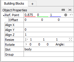
Figure 1: Object properties for multiple selected points.
Ref. Point and Offset
The reference point property shows the location of the handle. You can enter new actual coordinates or an offset to the current location. This helps position the handle more precisely than dragging the center point with the mouse. Moving the handle will cause the selected objects to move by the same amount.
- There are several ways to move the handle without moving the selection, in case you want to change the center point for a resize or rotate command:
- hold down the Alt key while dragging the handle; or
- Alt+click any location on a building block; or
- right-click the center dot of the handle to show the context menu, then choose “Relocate Handle To…” and enter precise coordinates.
When the handle is moved from its default location, the indicator to the right of the “Ref. Point” line will change its appearance (  ). Clicking the arrow will restore the handle to its default position.
Align X, Align Y, Align Z
When the selection includes a face, edge, or multiple points, the alignment fields appear. If all the points of the selection are already positioned at a single location along an axis, that location will be displayed in the corresponding alignment field.
Typing a value into one of the fields will cause all the points in the selection to move to that location on the axis.
Resize
The edit fields contain a scale multiplier for each axis. The values default to one, and when any are changed, the two buttons become enabled. The leftmost button resets the values back to one and the rightmost button causes resizing to occur. Pressing Return or Enter will also cause resizing along the 3 axes.
Selected objects are resized relative to the position of the handle/reference point.
Rotate
Rotation is done using the reference point (handle) as the center of rotation. The axis of rotation is specified by the X, Y and Z fields. When an angle is entered, the selected objects are rotated.
You can use a selected edge to define an axis of rotation. With an edge selected, click the import button (  ) next to the axis fields. Then enter an angle to do the rotation.
Group/Slot
Group names can be assigned to blocks, faces, edges, and points (but not control points). By assigning one group per slot, you can assign more than one group name to an object.
The context menu for blocks has commands for selecting, showing and hiding blocks by group.
See the topic Highlighting Groups for more information.
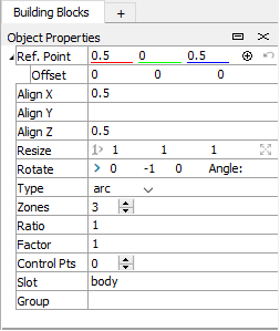
Figure 2: Object properties for a selected edge.
Type
When one or more edges are selected, the Type field appears. When all the selected edges are of the same type, the type name will appear (arc, polyline or spline). If the type of one of the edges is different, a dash appears. You can change the type of all the selected edges by choosing a type from the list.
Zones
The Zones field appears when one or more edges are selected. It shows the number of zones assigned for all the selected edges, or a dash if not all the edges have the same number of zones. Entering a number here will set the number of zones for all the selected edges.
Ratio
Ratio determines the relative lengths of zones along an edge.
The Ratio field appears when one or more edges are selected. It shows the ratio assigned to all the selected edges, or zero if not all edges have the same ratio. Entering a number here will set the ratio for all the selected edges.
Factor
Compared to Ratio, Factor is an alternate way of determining zone distribution. Factor is the relative size of the first zone along an edge compared to the size of the last zone.
The Factor field appears when one or more edges are selected. It shows the factor assigned to all the selected edges, or zero if not all edges have the same factor. Entering a number here will set the factor for all the selected edges.
Edge Ctrl Pts
The Edge Ctrl Pts field appears when one or more edges are selected. It shows the number of control points each selected edge has, or a dash if they don’t all have the same number. Entering a value will set the number of control points for all the selected edges.
This field also appears when one or more faces are selected, and operates on edges for the selected faces.
This is designed to be used in conjunction with the draping command to increase the resolution of edges for selected areas.
Face Ctrl Pts
The Face Ctrl Pts field appears when one or more faces are selected. It shows the dimensions (n x n) of the control point matrix for each selected face, or a dash if they don’t all have the same dimensions. Entering a value will set matrix dimensions for all the selected faces.
This is designed to be used in conjunction with the draping command to increase draping resolution for faces in selected areas.
Cycle
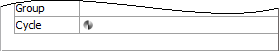
Figure 3: The Cycle control for a triangular face.
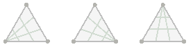
The Cycle control appears when a single face is selected and applies only to triangular faces. Clicking it will rotate the degenerate corner around a triangular face. (The three possible orientations are shown below.) This may be necessary for putting the model into a valid state to generate zones.
Reflect
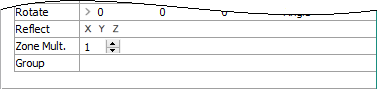
Figure 4: The Reflect and Zone Multiplier controls for blocks.
The Reflect controls appear when one or more blocks are selected and are enabled only when the selected blocks are not attached to any unselected blocks. Reflection causes the selected blocks to become a mirror image of themselves along the selected axis. Click either the X, Y or Z axis button to cause the blocks to be reflected.
Zone Mult.
The Zone Multiplier field appears when one or more blocks are selected. It shows the multiplier for all the selected blocks or a dash if not all the selected blocks have the same multiplier. Entering a value will set the zone multiplier for all the selected blocks.
Increasing the zone multiplier will not increase draping resolution.
Drape
When a geometric data set is loaded into a building blocks set, the Drape controls appear whenever one or more points, edges or faces are selected.
Draping causes points to move in a specified direction until they meet a polygon in a geometric data set.
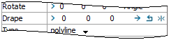
Figure 5: Drape controls for points, edges and faces.
The leftmost control lets you copy a vector from a selected edge to determine which directions the drape may occur in. You may also enter a vector directly into the edit fields.
The three buttons on the right cause draping to occur on selected points, edges or faces. One button causes draping in the direction of the specified vector. One causes draping in the opposite direction. The last button causes draping in both directions and does validation only once to save time. The draping command sent to the Console will always specify that points be draped no matter which type of object is selected in the Building Blocks pane.
View
Selection: Surface/Deep
The Selection controls let you switch between surface and deep selection, which is described here.
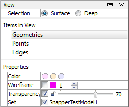
Figure 6: The View control set with Geometries selected.
The “Items in View” section lists the kinds of items in the Building Blocks pane that can have properties set for them.
Geometries
If any geometric data sets have been imported, the Geometries item will appear with the Properties section populated.
Color: Click one of the colored circles to set the displayed color of the geometric data.
Wireframe: These controls determine whether the wireframe is visible, what color it is, and how thick the lines are.
Transparency: These controls determine whether the geometric data is transparent and whether the transparency level is locked at or above 70 percent. The slider control can be moved with the mouse and the number can be edited.
Set: This section lists all the geometric data sets loaded into the program. A check mark next to a set name indicates that the geometric set is loaded into the current building blocks set.
Points and Edges
Controls are available for setting point size and line weight.
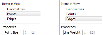
Figure 7: The View control set with Points or Edges selected.
| Was this helpful? ... | PFC © 2021, Itasca | Updated: Feb 25, 2024 |