
Operations in the Extrusion View
The extrusion view of the Extrusion pane is made visible by pressing the ( ) button on the toolbar. This view is used to determine the extent and zoning of the extrusion in the third (extruded) dimension. The basic operations involve defining extrusion length, splitting the length into distinct edges by adding points along the length, then specifying the edge zoning. This view is also used to specify how to orient the model in 3D model space. Note that as soon as information is put into the construction view, an estimate of the extent (that is, extrusion length) is created by default and applied. This estimate is adjusted accordingly as further operations in the Construction view change the model. As a result there will already be an initial length for the extrusion when first entering the Extrusion view.
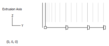
Figure 1: The extrusion view shows points and edges in the extruded dimension
The extrusion view presents a view plane that is perpendicular to the one shown in the construction view. In this view, the vertical line to the left represents the Construction view turned sideways. The total length of the extrusion is depicted starting from the square point at the left end of the horizontal line to the point at the right end of the line. There may also be intermediate points representing stages of the extrusion.
Operations in the extrusion view are described in the following topics:
When the necessary zoning information has been supplied in the extrusion view (and assuming operations are also complete in the construction view), the model is ready for extrusion. See the topic Performing the Extrusion for more information.
| Was this helpful? ... | PFC © 2021, Itasca | Updated: Feb 25, 2024 |