Simply Supported Isotropic Rectangular Plate under Combined Lateral and Direct Loads
Problem Statement
Note
To view this project in FLAC3D, use the menu command . Choose “VerificationProblems/ SimplySupportedIsotropicPlate” and select “SimplySupportedIsotropicPlate.prj” to load. The main data files used are shown at the end of this example. The remaining data files can be found in the project.
The deflection surface is determined for the case of a simply supported rectangular isotropic plate of
sides \(a\) and \(b\), subjected to a uniform lateral load, \(p_0\), and uniform tension,
\(N\). The plate is subjected to combined lateral and in-plane force systems. The lateral loading is
resisted by bending action, and the in-plane loading is resisted by membrane action. The problem
conditions are illustrated in Figure Figure #iplate-problem.
Closed-Form Solution
The analytic solution is given by Ugural (1981, pp. 155-156. The solution extends the small deformation theory of plates (whereby the deflection of the midsurface is assumed to be small relative to the plate thickness) to include the simultaneous action of the combined loading such that the midplane is strained subsequent to combined loading.
The deflection is given by
where \(D = {t^3 \over 12} \biggl({E \over {1 - \nu^2}}\biggr)\) is the flexural rigidity, \(t\) is the plate thickness, \(E\) is Young’s modulus, and \(\nu\) is Poisson’s ratio. The presence of a tensile (compressive) force decreases (increases) the plate deflection.
A 4 by 8 rectangular sheet of 3/4-inch plywood is characterized by
Denote the deflection at the plate center and the \(x\)-displacement along the edge at \(x = a\) by \((\Delta_z)_{\rm mid}\) and \(\Delta_x\), respectively. For this problem, \(\Delta_x\) is uniform along the edge. For a loading of \(p_0 = 1.0 \ {\rm kPa}\):
The given tensile force decreases the center deflection by an order of magnitude.
FLAC3D Model
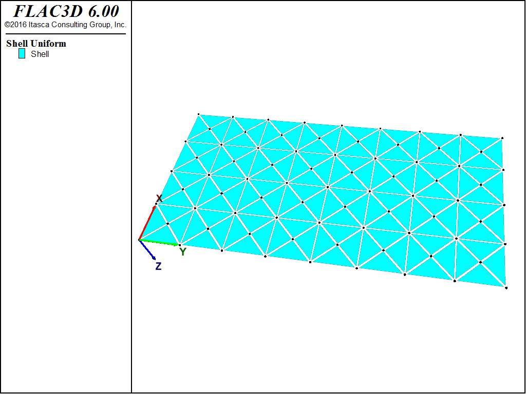
The FLAC3D model with a 4 by 8 mesh contains 128 shell elements, as shown in Figure 2.
The entire plate is modeled for clarity, although quarter-symmetry could be applied to reduce the model
size. All four edges have their \(z\)-velocities fixed at zero to simulate simple supports, and the
edge at \(x\) = 0 has its \(x\)-velocity fixed at zero to simulate a roller boundary condition.
The lateral loading is applied with the structure shell apply command, and membrane loading is
applied along the edge at \(x = a\) using the structure node apply force-edge command. A
cross-diagonal mesh pattern is utilized to ensure symmetric response, and the DKT-CSTH Hybrid shell
finite element is utilized to resist the combined membrane and bending actions. In order to inhibit
activation of spurious \(z\)-rotations along the edges, their \(z\)-rotational nodal velocities
are fixed to zero. This constraint is not necessary if the DKT-CST element is used. In order to model
the coupling, whereby the presence of a tensile membrane decreases the plate deflection, FLAC3D is run
in large-strain mode.
The theoretical and numerical solutions are compared along the three lines \(y = b/2\), \(x = a/2\), and \(x = a/4\). The theoretical values are obtained by taking the first 10 terms (\(m <= 21\) and \(n <= 21\)) of the infinite series. The numerical values for deflection are obtained from the nodes that lie along each line.
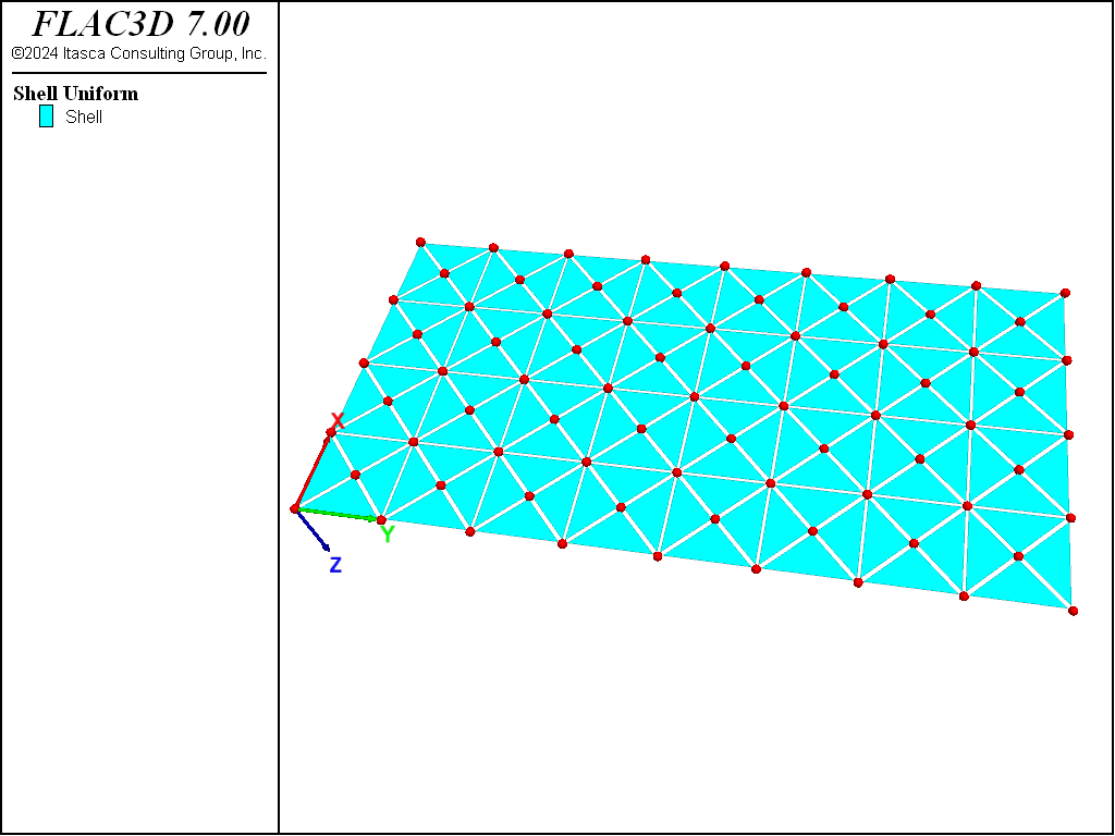
Figure 2: FLAC3D model for combined loading plate problem.
Results
The case \(N = 6.0 \times 10^5 \ {\rm N/m}\) is run to produce
which can be compared with the theoretical results above. The center deflection is within 0.8% of the theoretical value as shown in Figure 3 and compared with the theoretical solution along three lines in Figure 4 and Figure 5. The FLAC3D results compare well with the theoretical solution. These results demonstrate that the geometrically nonlinear stress-stiffening effect is modeled correctly by running FLAC3D in large-strain mode.
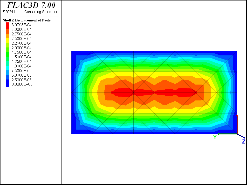
Figure 3: Deflection contours of plate (combined loading).
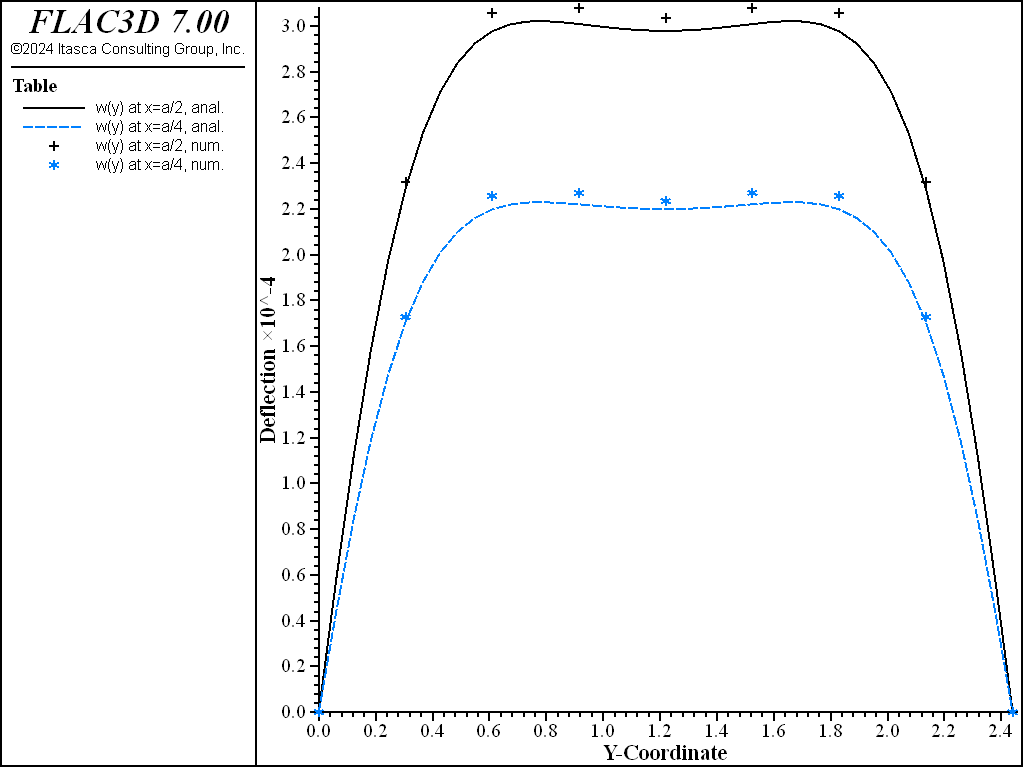
Figure 4: Deflection of plate along the lines \(x = a/2\) and \(x = a/4\) (combined loading).
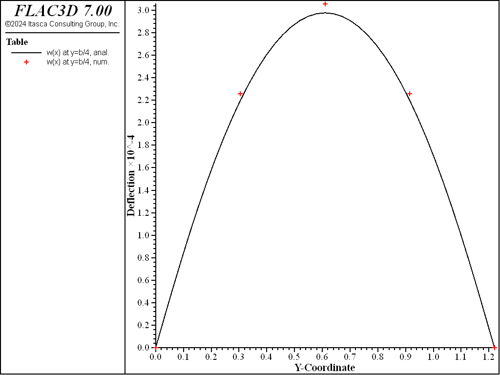
Figure 5: Deflection of plate along the line \(y = b/2\) (combined loading).
Reference
Ugural, A. C. Stresses in Plates and Shells. New York: McGraw-Hill Publishing Company Inc. (1981).
Data File
SimplySupportedIsotropicPlate.dat
; FLAC3D verification problem
; Isotropic rectangular plate under combined lateral and direct loads
model new
[t = 'Isotropic rectangular plate under combined lateral and direct loads']
model title [t]
; Create the elements and apply properties
struct shell create by-quadrilateral (0,0,0) (1.22,0,0) ...
                                     (1.22,2.44,0) (0,2.44,0) ...
                                     size (4,8) ...
                                     element-type=dkt-csth cross-diagonal
struct shell property isotropic (10e9,0) thick 19e-3
; simply supported condition on boundaries
struct node fix velocity-z rotation-z ...
    range union position-x 0.0 position-x 1.22 position-y 0.0 position-y 2.44
; rollers along x=0, foce along x=1.2
struct node fix velocity-x range position-x 0.0
struct node apply force-edge (6e5,0,0) range position-x 1.22
; Apply pressure
struct shell apply 1e3
; Set large strain on, creating coupling between bending and membrane
model large-strain on
; Solve the model
model solve ratio-local=1e-5
; Save the model
model save 'isotropic4x8'
| Was this helpful? ... | 3DEC © 2019, Itasca | Updated: Feb 25, 2024 |