Prediction of Borehole Closure in a Salt Formation
Problem Statement
Note
The project file for this example is available to be viewed/run in FLAC3D.[1] The main data file used is shown at the end of this example.
Two rooms and a cross-drift are mined in a salt formation at a depth of about 600 m below the ground surface. A horizontal borehole is drilled in the pillar separating the two rooms. The creep closure of this borehole is driven by the shear stresses induced by the excavation process. Closure is estimated in this example using the WIPP-reference model for the salt. The simulation covers a period of 7.7 years and accounts for the instantaneous mining and drilling events at time zero. This example problem is a simplified model of the Intermediate Scale Borehole Test performed by Sandia National Laboratories (see Argüello, 1991).
Modeling Procedure
The plane perpendicular to the borehole axis and located halfway between the rooms is a plane of symmetry for this problem. A system of coordinate axes is selected with its origin on the symmetry plane, the \(x\)-axis is oriented along the borehole axis, and the \(z\)-axis pointing upward. The domain under consideration is bounded by the symmetry plane and five far-field planes, with two horizontal planes located at \(|z|\) = 53.36 m and three vertical planes at \(|y|\) = 44.51 m and \(x\) = -39.62 m. The layout of the room, drift, and borehole is presented in Figure 1, with the plane of symmetry in front and the top half of the model removed for illustration. The test room is 5.49 m wide by 5.49 m high and 30.48 m long; its axis runs parallel to the symmetry plane. The cross-drift is 4.27 m wide by 3.66 m high and cuts through the model. The borehole drilled through the pillar is 0.91 m in diameter, 9.14 m long, and located approximately 1.57 m above the floor at the mid-length of the room.
The boundary conditions include an applied pressure of 13.57 MPa across the top of the model, to represent loading from the overburden, and roller boundaries on the sides. Gravity loading is included in the calculation with a mass density of 2300 kg/m3 for the rock and a gravitational acceleration of 9.79 m/sec2. The initial stress-state is lithostatic (i.e., isotropic with a linear depth variation). The test room, cross-drift, and borehole are assumed to be excavated instantaneously at time \(t\) = 0. The temperature is held constant at 300 K throughout the entire 7.7 year simulation.
It is assumed that the formation is composed entirely of halite, modeled using a WIPP model with several properties:
| bulk modulus, \(K\) | 1.65 GPa |
| shear modulus, \(G\) | 1.00 GPa |
| WIPP-model exponent, \(n\) | 4.90 |
| WIPP-model constant, \(D\) | 5.79 × 10-36 Pa-4.9 s-1 |
| activation energy, \(Q\) | 12,000 cal/mol |
| WIPP-model constant, \(A\) | 4.56 |
| WIPP-model constant, \(B\) | 127.0 |
| secondary creep rate, \(\dot {\epsilon}_{ss}^*\) | 5.39 × 10⁻⁸ s-1 |
The universal gas constant, \(R\) (also used in the model), has the value 1.987 cal/mol-K.
The FLAC3D model shown in Figure 1 and Figure 2 is created from three layers of zones running parallel to the symmetry plane; the layers correspond to the pillar, room, and far-field regions. Each layer is composed of radial-cylinder primitive shapes in the vicinity of the borehole and brick primitive shapes farther out. A close-up view of the borehole region is shown in Figure 3. Primitives are generated in the domain corresponding to positive values of the \(y\)- and \(z\)-coordinates and then reflected across the \(z\) = 0 and \(y\) = 0 planes. The final grid has a total of 4896 zones.
The WIPP model with the properties listed above is assigned to the zones. Note that the temperature is initialized for this run as a zone property. Salt density and components of the gravity vector are specified, and the large-strain mode is selected. The stresses are initialized to correspond to a lithostatic stress-state, and the roller-type and pressure boundary conditions are applied. Histories of gridpoint displacements are taken in the \(y\)- and \(z\)-directions at four locations along the borehole axis corresponding to \(x\) = 0, \(x\) = -3.5 m, \(x\) = -6.1 m and \(x\) = -9.14 m. The pillar response is also monitored by taking histories of the vertical displacements at the pillar roof and floor at two points (C and B) along the drift, and two points (D and A) along the borehole axis, located at \(x\) = 0 and \(x\) = -9.14 m, respectively.
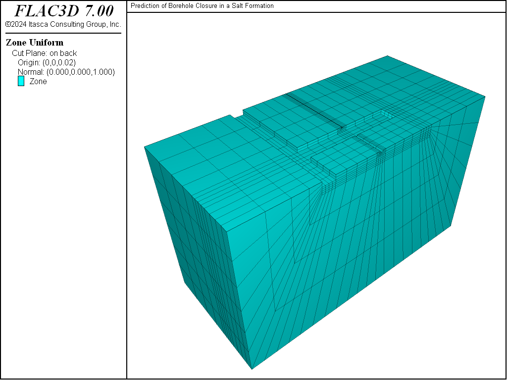
Figure 1: Model geometry—bottom half.
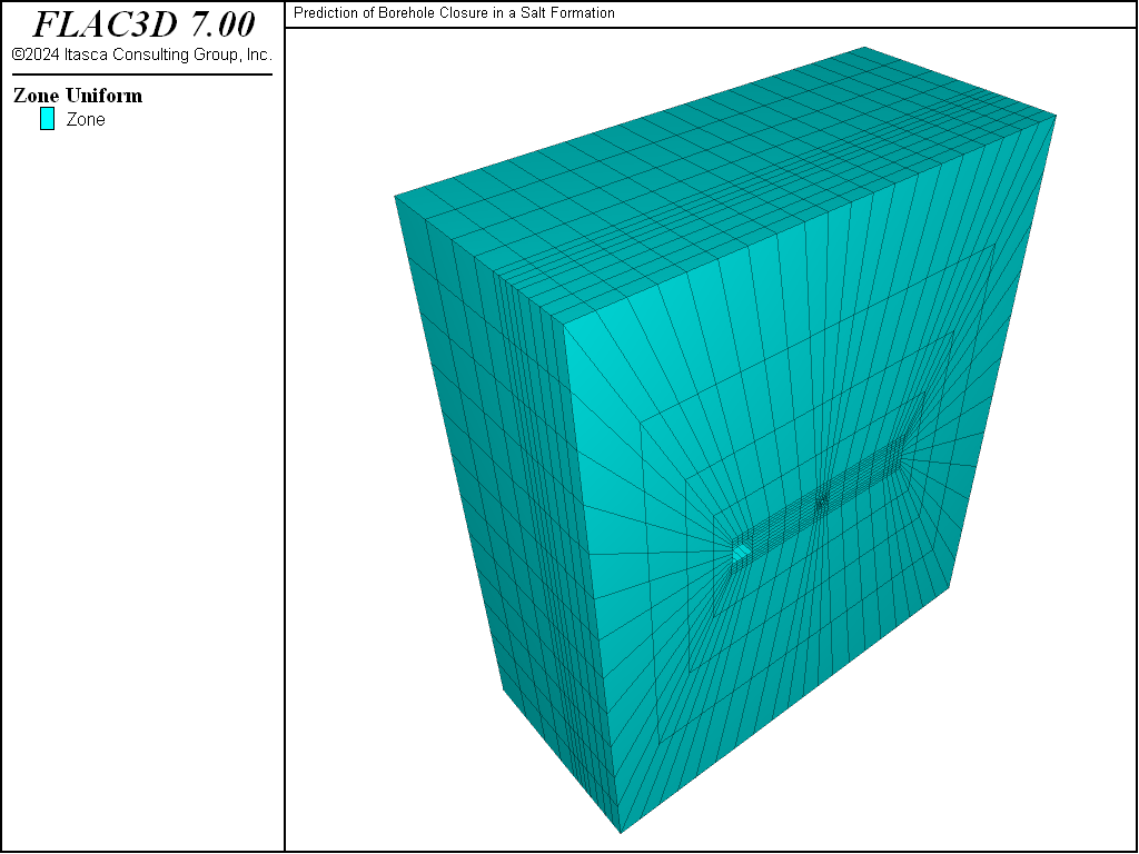
Figure 2: Model geometry—front view.

Figure 3: Borehole region.
Instantaneous excavation of the drift room and borehole is simulated by assigning the null model to the zones located in the corresponding volumes. The creep behavior is prevented by setting model creep active to off, and the model is cycled to equilibrium (corresponding to an average force ratio of 1e-5) to establish the initial “instantaneous” elastic response of the system (at the time scale of the creep process).
The creep response is then requested by setting model creep active to on. The creep timestep is initialized at 200 seconds, and the upper bound for its value is set to 40,000 seconds. The automatic timestep selection is activated by setting model creep timestep automatic to on. The model is cycled to an age of 7.7 years before the results are analyzed.
The model requires approximately 261 MB RAM and takes roughly 1 minute to run the complete simulation on a 3.4 GHz Intel i7 computer.
Discussion
Figure 4 shows displacement histories at points C, D, B, and A at the pillar floor and roof. At the end of the simulation, the pillar shortening, defined as the relative vertical displacement between roof and floor, is largest (with a value of approximately 17.6 cm) at the intersection of room and drift (point B), and smallest (with a value of approximately 6.6 cm) at the center of the pillar (point D). It is approximately 9 cm at the borehole end (point A) and 10.5 cm at the pillar mid-length along the drift (point C).
The borehole deformation is shown in Figure 5 and Figure 6, where vertical and horizontal displacements of the borehole walls are plotted after 7.7 years at four locations along the borehole length, corresponding to \(x\) = 0, \(x\) = -3.5 m, \(x\) = -6.1 m, and \(x\) = -9.14 m. The vertical closure is seen to decrease from the pillar center to the room, with estimated values of 10.3 cm, 9.4 cm, 8.6 cm, and 7.8 cm at each of the preceding locations. The vertical closure follows the same trends with values of 9.7 cm, 8.7 cm, 6.3 cm, and 4.2 cm, respectively. The preceding values indicate that an ovalling of the hole, which is less pronounced as the center of the pillar is approached, takes place. The borehole floor elevation appears to be increasing, and its axis appears to bend to the left from the pillar center toward the room.
Displacement contours around the borehole near the pillar center are plotted in Figure 7. The displacement contours in a vertical plane around the room and borehole are shown in Figure 8, and those around the room and drift in Figure 9, 7.7 years after the excavation.
Although the actual numbers quoted in this example should be analyzed with great caution given the relatively small number of zones used along the borehole axis, they seem to reflect the general trend observed in the Intermediate Scale Borehole Test referenced at the beginning of this example. It should be emphasized, though, that the model is intended as an example. Issues that may affect the borehole closure, such as excavation sequencing, tunnel support, and stratigraphy, are not addressed.
References
Argüello, J. G. Pretest 3D Finite Element Analysis of the WIPP Intermediate Scale Borehole Test, Sandia National Laboratories, SAND90-2055 (1991).
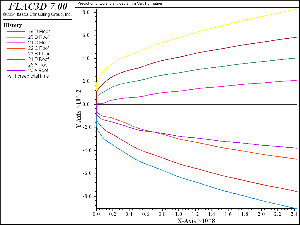
Figure 4: Roof and floor displacements.
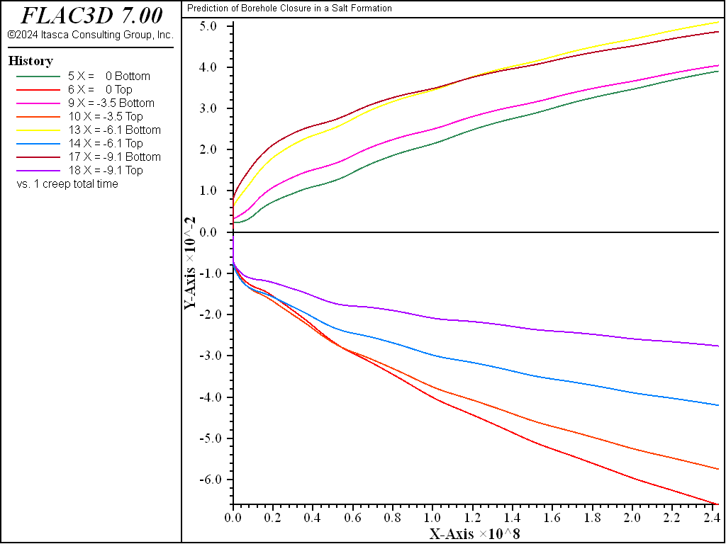
Figure 5: Borehole vertical displacements at four locations along the borehole axis.
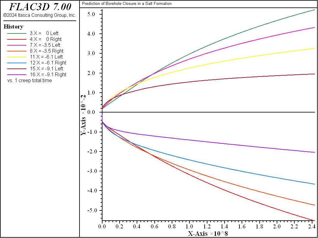
Figure 6: Borehole horizontal displacements at four locations along the borehole axis.
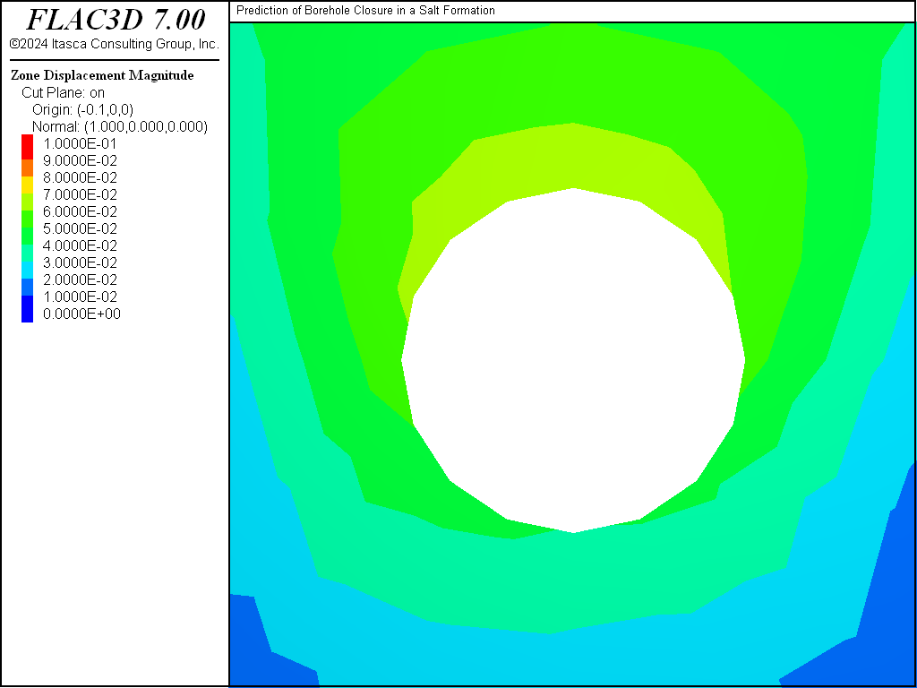
Figure 7: Displacements around the borehole at \(x\) = 0.
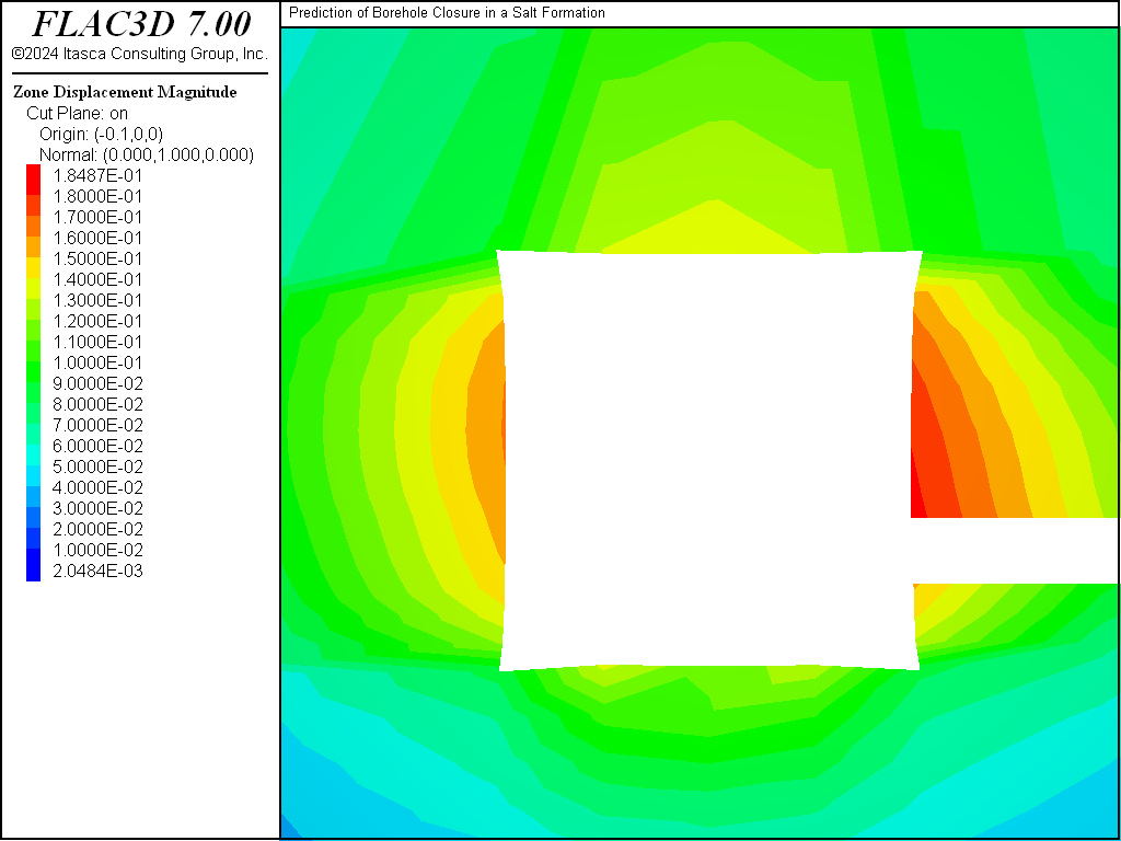
Figure 8: Displacement contours around the room and borehole.
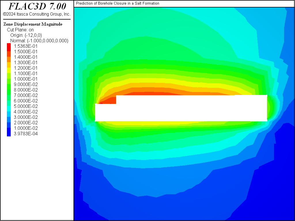
Figure 9: Displacement contours around the room and drift.
Data File
BoreholeClosureInSaltFormation.dat
;-------------------------------------------------------------------
;                Prediction of Borehole Closure
;                in a Salt Formation
;-------------------------------------------------------------------
model new
model title 'Prediction of Borehole Closure in a Salt Formation'
model configure creep
; create geometry built interactive in Building Blocks
; and exported from the State Pane
program call "geometry" suppress
zone generate from-building-blocks
; --- group definitions ---
zone group 'drift' range position (-39.63,-19.51,-1.57) (0,-15.24,2.09)
zone group 'room' range position (-14.63,-15.24,-1.57) (-9.14,15.24,3.92)
zone group 'bhole' range cylinder end-1 (0,0,0) end-2 (-9.14,0,0) rad 0.46
zone group 'empty' slot 'excav' range group 'drift' or 'room' or 'bhole'
; --- mechanical model ---
zone cmodel assign wipp
zone property shear 1.e9 bulk 1.65e9 density 2300
zone property constant-gas 1.987 activation-energy 12e3 ...
exponent 4.9 constant-d 5.79e-36
zone property constant-a 4.56 constant-b 127 ...
creep-rate-critical 5.39e-8 temperature 300
; --- settings ---
model gravity (0,0,-9.79)
model large-strain on
; --- initial conditions ---
zone initialize-stresses overburden -13.57e6
; --- boundary conditions ---
zone face skin ; Label outer boundaries
zone face apply velocity-normal 0 range group 'Top' not
zone face apply stress-normal -13.57e6 range group 'Top'
; --- take some histories ---
history interval 10
model history creep time-total
model history mechanical ratio-local
zone history displacement-y position ( 0   ,-.46, 0   ) ...
label "X =    0 Left"
zone history displacement-y position ( 0   , .46, 0   ) ...
label "X =    0 Right"
zone history displacement-z position ( 0   ,0   , -.46) ...
label "X =    0 Bottom"
zone history displacement-z position ( 0   ,0   ,  .46) ...
label "X =    0 Top"
zone history displacement-y position (-3.5 ,-.46, 0   ) ...
label "X = -3.5 Left"
zone history displacement-y position (-3.5 , .46, 0   ) ...
label "X = -3.5 Right"
zone history displacement-z position (-3.5 ,0   , -.46) ...
label "X = -3.5 Bottom"
zone history displacement-z position (-3.5 ,0   ,  .46) ...
label "X = -3.5 Top"
zone history displacement-y position (-6.1 ,-.46, 0   ) ...
label "X = -6.1 Left"
zone history displacement-y position (-6.1 , .46, 0   ) ...
label "X = -6.1 Right"
zone history displacement-z position (-6.1 ,0   , -.46) ...
label "X = -6.1 Bottom"
zone history displacement-z position (-6.1 ,0   ,  .46) ...
label "X = -6.1 Top"
zone history displacement-y position (-9.14,-.46, 0   ) ...
label "X = -9.1 Left"
zone history displacement-y position (-9.14, .46, 0   ) ...
label "X = -9.1 Right"
zone history displacement-z position (-9.14,0   , -.46) ...
label "X = -9.1 Bottom"
zone history displacement-z position (-9.14,0   ,  .46) ...
label "X = -9.1 Top"
;D
zone history displacement-z position (0,-15.24,-1.57) label "D Floor"
zone history displacement-z position (0,-15.24, 2.09) label "D Roof"
;C
zone history displacement-z position (0,0,-1.57) label "C Floor"
zone history displacement-z position (0,0, 2.09) label "C Roof"
;B
zone history displacement-z position (-9.14,-15.24,-1.57) label "B Floor"
zone history displacement-z position (-9.14,-15.24, 2.09) label "B Roof"
;A
zone history displacement-z position (-9.14,0,-1.57) label "A Floor"
zone history displacement-z position (-9.14,0, 2.09) label "A Roof"
; --- instantaneous excavation of drift, room and borehole ---
zone cmodel assign null range group 'empty'
; --- small time elastic response ---
model creep active off
model solve
model save 'wipe1_a'
zone gridpoint initialize velocity (0,0,0)
; --- creep response ---
model creep active on
model creep timestep minimum 1e-20
model creep timestep maximum 4.e4
model creep timestep upper-multiplier 1
model creep timestep auto
model solve time-total 179755200  ;---> age       5.7 year
model save 'wipe1_b'
model solve time-total 242827200  ;---> total age 7.7 year
model save 'wipe1_c'
Endnotes
| [1] | To view this project in FLAC3D, use the program menu.
⮡ FLAC3D |
| Was this helpful? ... | 3DEC © 2019, Itasca | Updated: Feb 25, 2024 |