Simple Test of Geogrid-Soil Interface Behavior
Problem Statement
Note
The project file for this example is available to be viewed/run in FLAC3D.[1] The main data files used are shown at the end of this example. The remaining data files can be found in the project.
A geogrid is embedded in a soil block and then pulled out of the block. The soil is represented by a single zone, and the geogrid is represented by a single geogrid element. The shear stress and shear displacement of one of the coupling springs is monitored and plotted to demonstrate the effects of the geogrid-soil interface properties on system response.
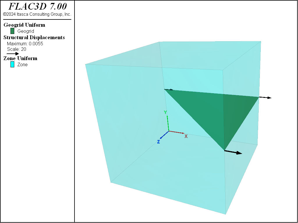
The FLAC3D model consists of one geogrid element embedded in one zone, as shown in Figure 1. The geogrid is initially created, using the structure geogrid create by-triangle command, to be a single triangle embedded in the zone. The zone is assigned elastic properties, and is fully fixed in all directions. The geogrid is assigned isotropic material properties and a thickness, and a constant velocity of 1 × 10⁻⁶ m/step in the global \(x\)-direction is applied to all geogrid nodes. The shear stress and total shear displacement in a coupling spring are monitored using the structure geogrid history command. The geogrid-soil interface properties are then varied to demonstrate their effects on the system behavior.
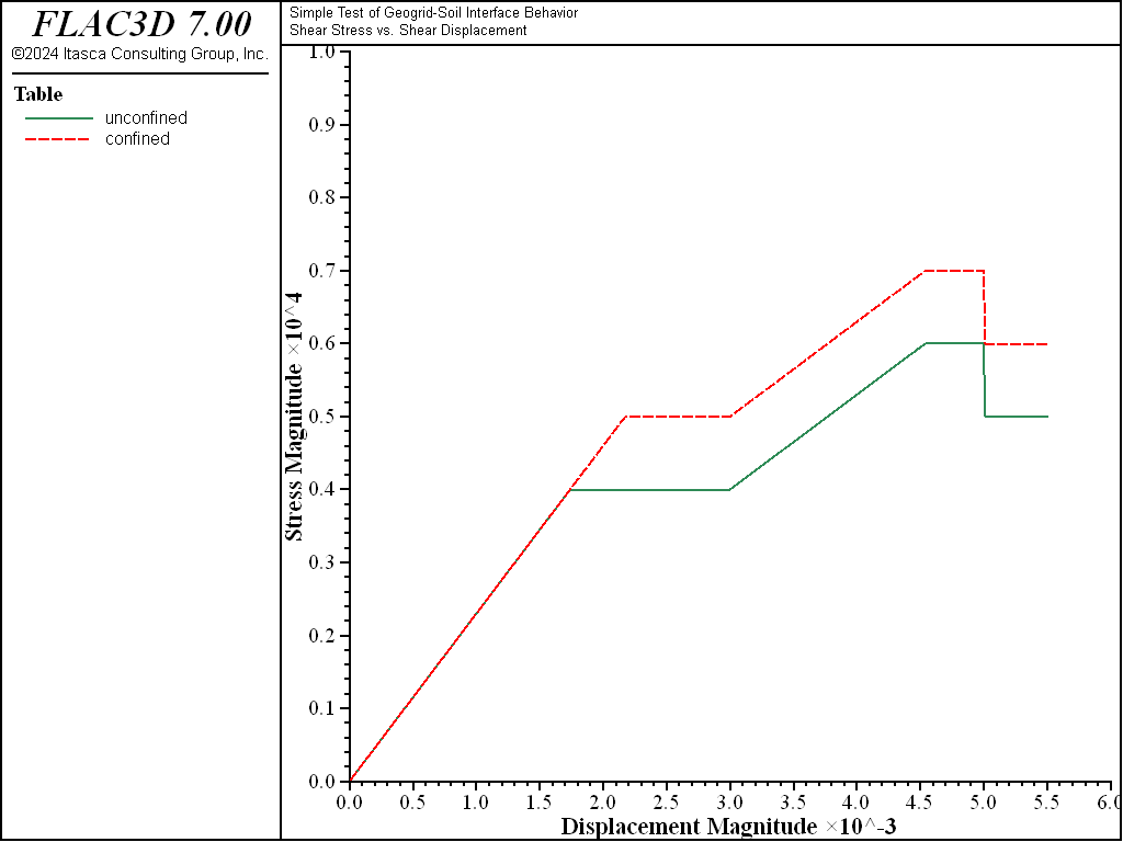
The shear stress versus total shear displacement for the two cases is shown in Figure 2. The peak shear stress is given by (see Shear-directional interface behavior for geogrid elements)
| where: | \(c\) | = | coupling spring cohesion; |
| \(\sigma_m\) | = | effective confining stress; and | |
| \(\phi\) | = | coupling spring friction angle. |
For the initial properties specified, the case with zero and 1.73 kPa confining stress give expected peak shear stresses of 4 and 5 kPa, respectively. The effect of the specified confinement is to raise the response plots by 1 kPa, and this is what is found. Also, the slope of these curves equals the coupling spring stiffness per unit area (structure geogrid property coupling-stiffness). When any of the geogrid properties are modified, the system responds accordingly.

Figure 2: Shear stress versus total shear displacement (unconfined and confining stress of 1.73 kPa).
Data File
SoilInterfaceTest.dat
model new
model title "Simple Test of Geogrid-Soil Interface Behavior"
; Test case 1, confining stress = 0
[global confiningStress = 0]
program call 'PerformTest'
history export '1' vs '2' table 'unconfined'
model save 'SoilInterfaceTest0'
; Reset
zone delete
struct geogrid delete
history delete
; Test case 2, confining stress = -1.73e3
[confiningStress = -1.73e3]
program call 'PerformTest'
history export '1' vs '2' table 'confined'
model save 'SoilInterfaceTest173'
PerformTest.dat
model large-strain off
; One zone test
zone create brick size=(1,1,1)
; Assign material model and properties
zone cmodel assign elastic           ; for the rock, sandy shale
zone property bulk=3.33e9 she=2.5e9  ; for the rock, E=6 GPa, nu=0.2
; Initialize confining stress
zone initialize stress-yy=[confiningStress] ; apply confining stress,
                                            ; zero or -1.73e3
; Fix all zone gridpoints
zone gridpoint fix velocity
; Create triangular geogrid, and assign properties
struct geogrid create by-triangle (0,0.5,0) (1,0.5,0) (1,0.5,1)
struct geogrid property thickness=0.1 isotropic=( 20e9, 0.2) ...
                        coupling-stiffness=2.3e6 coupling-cohesion=4e3 ...
                        coupling-friction=30.0
; Take some histories
struct geogrid history coupling-stress position (0.5,0.5,0.3)
struct geogrid history coupling-displacement position (0.5,0.5,0.3)
; Fix structural node velocities
struct node fix velocity
struct node initialize velocity-x 1e-6 local
; Cycle
model cycle 3000 ; 3e-3 total displacement
; Update coupling properties
struct geogrid property coupling-cohesion=6e3 coupling-stiffness=1.3e6
model cycle 2000 ; 5e-3 total displacement
; Update coupling properties
struct geogrid property coupling-cohesion=5e3
model cycle 500 ; 5.5e-3 total displacement
Endnotes
| [1] | To view this project in FLAC3D, use the program menu.
⮡ FLAC |
| Was this helpful? ... | 3DEC © 2019, Itasca | Updated: Feb 25, 2024 |

