Embedded Retaining Wall
Problem Statement
Note
To view this project in FLAC3D, use the menu command . Choose “Structure/Liner/EmbeddedRetainingWall” and select “EmbeddedRetainingWall.prj” to load. The main data files used are shown at the end of this example. The remaining data files can be found in the project.
The following example illustrates the use of the embedded liner to simulate a retaining wall (e.g., a sheetpile wall). The soil/wall properties chosen for this example are for demonstration purposes; actual values for wall friction and adhesion can be found in the literature (e.g., Clayton et al. 1993).
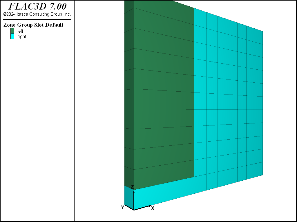
The initial geometry for this example is shown in Figure 1.
The model uses zone initialize-stresses to initialize stresses due to gravitational loading, and
the liner coupling springs are initialized with the structure liner initialize coupling command.
Note that while this command accounts for the stress state in the surrouding zones, some cycling must take
place to account for the gravitational weight of the liners.
The model is stepped to an equilibrium state with the embedded liner within the grid. Then the
zone relax excavate command is use to excavate in a way that does not cause spurious tensilve
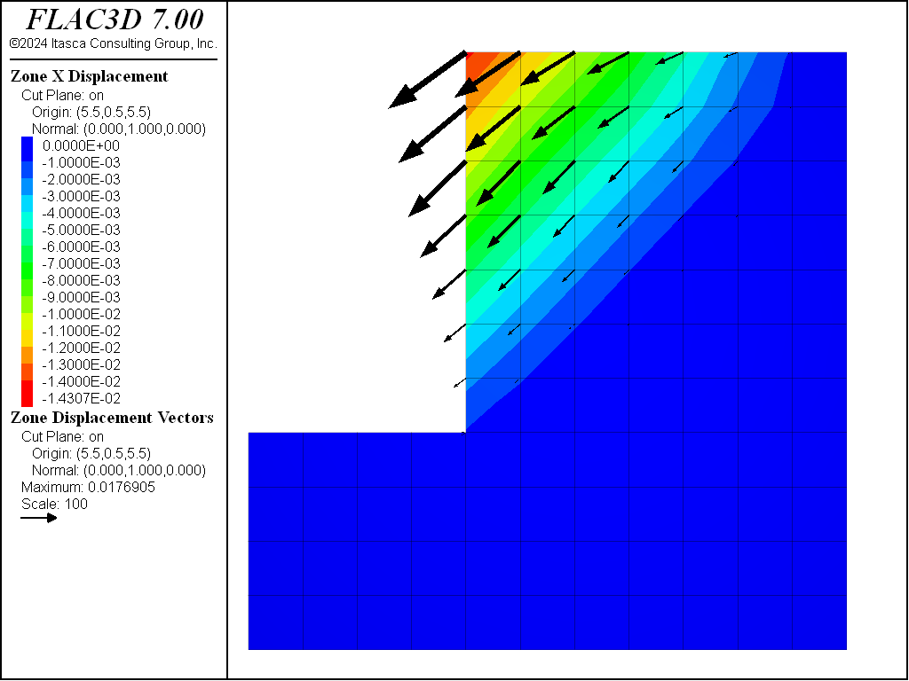
failure, and the model is stepped to equilibrium again. The resulting displacements in the soil are
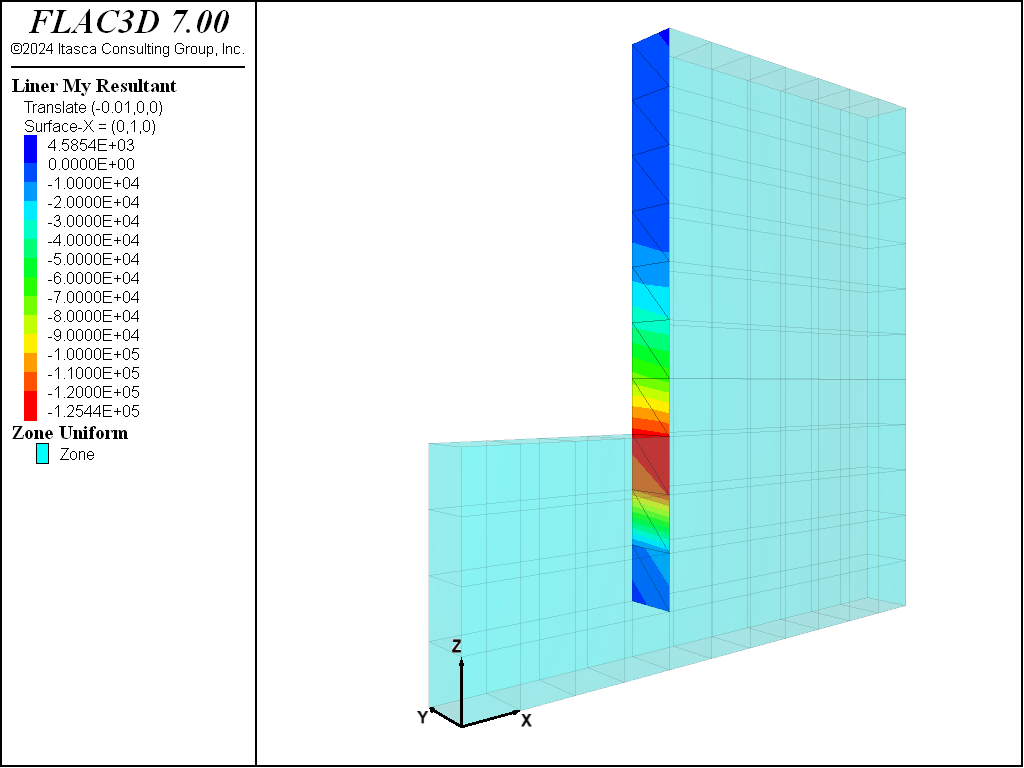
plotted in Figure 2. The moment distribution in the wall is shown in
Figure 3.
Reference
Clayton, C. R. I., J. Milititsky and R. T. Woods. Earth Pressure and Earth-Retaining Structures, pp. 145-148. London: Blackie Academic & Professional (1993).
Data File
EmbeddedRetainingWall.dat
; Liner example application Embedded Retaining Wall
model new
model large-strain off
model title 'Demonstration of Embedded Liner'

; Create the soil.
zone create brick size 11,1,11 group 'right'
zone cmodel assign mohr-coulomb
zone prop bulk=5e9 shear=1e9 density 2000 cohesion 1e4 friction 30 tension 0
model gravity 10
; Name regions
zone group 'left' range position-x 0 4 position-z 1 50
zone face group 'Liner' internal ...
                        range group 'right' group 'left' position-z 1.0 not
; Initial conditions
zone initialize-stresses ratio 0.6,0.4
; Boundary conditions
zone gridpoint fix velocity-x range union position-x=0 position-x=11
zone gridpoint fix velocity-y
zone gridpoint fix velocity-z range position-z=0
; create the embedded liner
; (side1 and and side2 properties are assumed to be the same)
struct liner create by-zone-face separate range group 'Liner'
struct liner property isotropic=( 2e9, 0.25) thickness=1.0  density 2000
struct liner property coupling-stiffness-normal=1e11 ...
             coupling-stiffness-shear=1e11 coupling-yield-normal=0.0 ...
             coupling-cohesion-shear=0 coupling-cohesion-shear-residual=0 ...
             coupling-friction-shear=30.0
struct liner property coupling-stiffness-normal-2=1e11 ...
             coupling-stiffness-shear-2=1e11 coupling-yield-normal-2=0.0 ...
             coupling-cohesion-shear-2=0 ...
             coupling-cohesion-shear-residual-2=0 ...
             coupling-friction-shear-2=30.0
struct liner initialize coupling
model save 'Start'
; Solve to equilibrium
model solve convergence 1
model save 'Initial'
; Excavate
zone relax excavate range position-x 0 4 position-z 4 50
;zone cmodel assign null range position-x 0 4 position-z 4 50
struct liner property slide=on
model solve convergence 0.1
model save 'Weaken'
| Was this helpful? ... | 3DEC © 2019, Itasca | Updated: Feb 25, 2024 |


