Hybrid Bolt Structural Elements
Hybrid bolts encompass the behavior of cables but include an extra component to resist shearing perpendicular to the cable where the cable crosses a joint or interface.
Basic cable elements do not resist shearing perpendicular to the cable. However, when cables are used to simulate bolts, it is well known that bolts crossing joints will provide some resistance to shearing on the joints. Dight (1982) suggests five different mechanisms that contribute to this effect.
- An increase in shear resistance due to lateral resistance developed by the rockbolt via dowel action
- An increase in normal stress as a result of pre-stressing of the rockbolt
- An increase in normal stress as a result of axial force developed in the rockbolt from dilatancy of the joint
- An increase in normal stress as a result of axial force developed in the rockbolt from lateral extension
- An increase in shear resistance due to axial force in the rockbolt resolved in the direction of the joint
Cables will demonstrate effects 2 – 5, but not 1. The dowel action is really an umbrella term for a set of complex mechanical effects including bending of the steel bolt, crushing of the grout, crushing of the host rock, etc. (see Figure 1). No attempt is made to reproduce all of these effects in 3DEC. Instead, the dowel effect is simulated simply by a shear spring that resists slip on the fault where it is crossed by the bolt. The hybrid bolt is therefore a combination of cable element and reinforcement element.
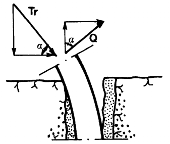
Figure 1: Resistance mechanism of a rock joint reinforced by means of a dowel (from Ferrero, 1995).
Mechanical Behavior
The formulation of the cable portion is exactly as described in Cable Structural Elements. The mechanical behavior of the dowel segments is described here. The following description is modified from Lorig (1985).
Experimental results and theoretical investigations indicate that shearing along a discontinuity induces bending stresses in the reinforcement that decay very rapidly with distance into the rock from the shear surface. Typically, the bending stresses are insignificant within one to two reinforcing element diameters. The short length of reinforcement that spans the discontinuity and changes orientation during shear displacement is referred to as the active length. Methods for estimating the active length are presented below.
The model may be considered to consist of a spring located at the discontinuity interface and oriented parallel to the interface, as shown in Figure 2. Following shear displacement, the shear spring remains perpendicular to the original orientation. Note that the spring representing the dowel segment is not oriented perpendicular to the bolt as might be expected. This is because a spring oriented in this way would produce resisting forces when the discontinuity opens purely in tension. This would then result in too much resistance to opening since the cable component is already resisting opening. The dowel segment therefore is oriented to only resist shearing on the joint.
The shear force-displacement relation is described in incremental form by the expression
where:
\(\Delta F_s\) is an incremental change in shear force;
\(\Delta u_s\) is an incremental change in shear displacement; and
\(K_s\) is the shear stiffness.
The maximum force is limited by a shear strength (in force units). A rupture limit can also be specified for the shear force. If the relative shear strain in the reinforcement element exceeds a specified strain limit, then the shear force will be set to zero. The shear strain is defined as the shear displacement divided by the active length.
Implementation
The dowels are simulated with two nodes on either side of a discontinuity. The nodes are rigidly connected to the zones. A second link also exists between the two nodes that uses a Pile Yield constitutive model in the non-axial directions. The nodes are spaced a small distance apart (0.1% of the bolt length) so that the local coordinate system can be determined. The nodes are always placed such that the local direction is perpendicular to the discontinuity, not necessarily parallel to the bolt. See #fnum`Figure # The dowel force calculations proceed independently of the host cable calculations. The only interaction is if the dowel ruptures in shear, then the host cable element also ruptures, so that the segment carries no load.
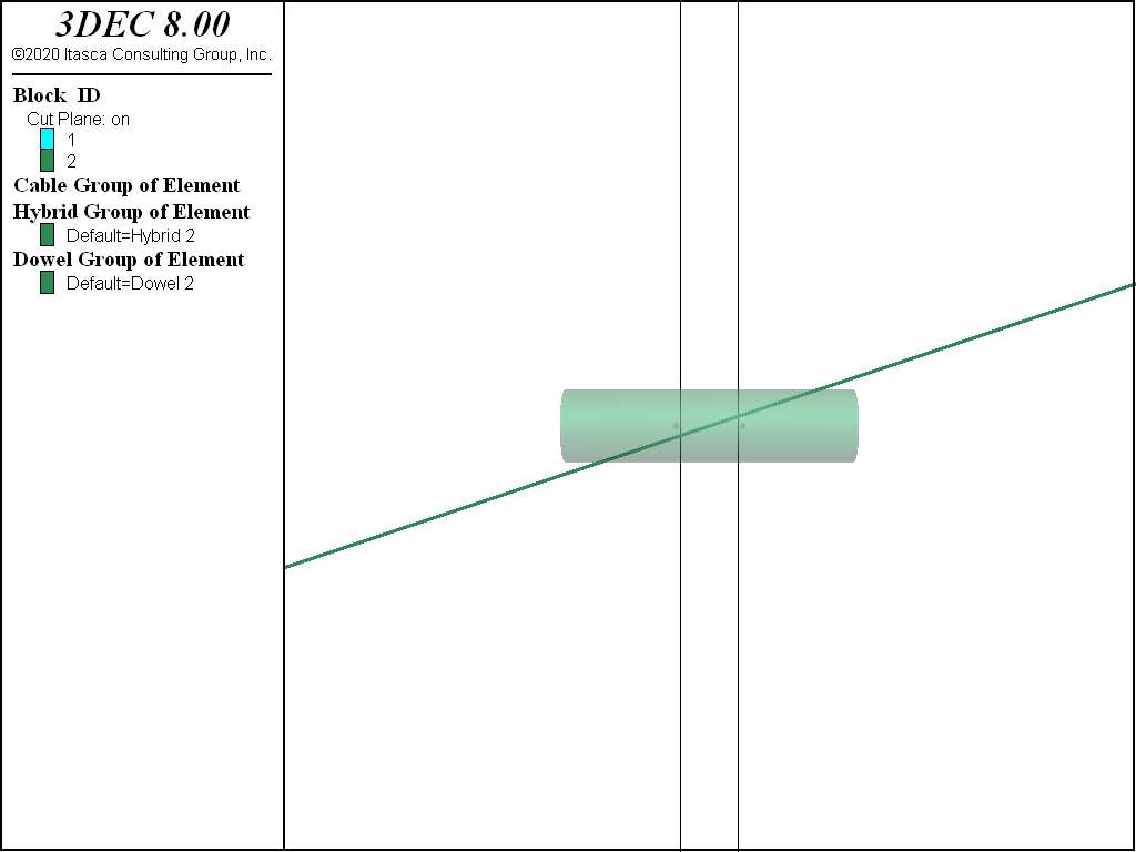
Figure 2: A hybrid bolt crossing a discontinuity at an angle. The dowel is plotted with a length equal to the active length. The nodes used in the dowel calculation are shown on either side of the open joint.
Properties
Each hybrid bolt element has 13 properties (the same as cable elements):
- density, mass density, \(ρ\) (optional — needed if dynamic mode or gravity is active) [M/L3]
- young, Young’s modulus, \(E\) [F/L2]
- yield-compression, compressive yield strength (force units), \(F_c\) [F]
- yield-tension, tensile yield strength (force units), \(F_t\) [F]
- tensile-failure-strain, tensile failure strain, \(\varepsilon_f\) [-] (only active if assigned a positive value)
- thermal-expansion, thermal expansion coefficient , \(\alpha_t [1/T]\) (optional — used for thermal analysis)
- cross-sectional-area, cross-sectional area, \(A\) [L2]
- grout-cohesion, grout cohesion (force units) per unit length, \(c_g\) [F/L]
- grout-friction, grout friction angle, \(ϕ_g\) (degrees)
- grout-stiffness, grout stiffness per unit length, \(k_g\) [F/L2]
- grout-perimeter, grout exposed perimeter, \(p_g\) [L]
- slide, large-strain sliding flag (default: off)
- slide-tolerance, large-strain sliding tolerance
The material behavior is described by properties 1–6, the cross-sectional geometry is described by property 7, and the coupling behavior is described by properties 8–13.
The dowel segments have 4 properties:
- dowel-active-length, Dowel active length, [-]
- dowel-stiffness, Dowel shear stiffness, \(K_s\) [F/L]
- dowel-strength, Dowel shear strength, [F]
- dowel-failure-strain, Dowel shear failure strain, [-]
Calibration
Influence of Segment Length and Dowel Length
For a fixed set of parameters, changing the node spacing mostly influences the rupture displacement in axial and shear — easy to readjust by changing the axial and shear critical strain — but also the stiffness of the bolt. Indeed, for a given shear or axial joint displacement/opening, the smaller the node spacing, the stiffer the bolt reaction will be due to an increase in component (4) described above (increase in normal stress as a result of axial force developed in the rockbolt from lateral extension). One can adjust the shear and axial stiffness then, but there is a limitation to the calibration process: the smaller the segment, the larger the influence of the axial stiffness on the shear response of the bolt. Indeed, the smaller the node spacing, the larger the axial strain becomes for a given joint shear displacement relative to the shear strain. This is a geometric effect that the calibration can not overcome.
Overall, it is important to realize that the micro-axial behavior strongly influences the macro-shear behavior of the bolt.
The Calibration Steps
The hybrid bolt model properties are typically calibrated through simple shear and pullout tests on bolts perpendicular to the joint (see example below).
Table 1 presents the parameters that should be defined before performing the calibration and held constant during a simulation for the calibration to remain valid.
| 3DEC Parameter | Description | Depends on |
|---|---|---|
cross-sectional-area |
Cross-sectional area of cable | Support design |
grout-perimeter |
Perimeter of the hole. Only required if grout-friction > 0 |
Borehole diameter |
segment-length |
Hybrid bolt node spacing | Geometry of the model used to model the rock mass. segment-length should be small enough to have at least one or two nodes between discontinuities |
dowel-active-length |
Length of dowel segments in a hybrid bolt | Same as segment-length |
grout-friction |
Optional parameter. Friction angle of the grout material [degrees] | Grout properties |
Figure 3 presents typical simple shear test results and associated stages. Simple shear tests are the classical tests used to study (and in this case calibrate) bolt behavior in shear.
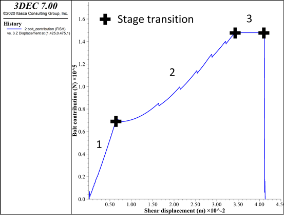
Figure 3: Hybrid bolt calibration. Typical simple shear test curve and associated stages.
Table 2 presents the critical parameters to adjust in order to obtain the desired behavior for hybrid bolts during a simple shear test.
| Stage | Primary Influence | Secondary Influence |
|---|---|---|
| Elastic stage (1) | dowel-stiffness |
young grout-stiffness |
| End of elastic stage | dowel-yield |
|
| Yield stage (2) | grout-stiffness |
young |
| End of yield stage/Plastic stage (3) | grout-cohesion |
yield-tension |
| End of plastic stage | dowel-failure-strain |
Figure 4 presents typical simple pull test results and associated stages. Pull tests are the classical tests used to study, and in this case calibrate, bolt behavior in tension.
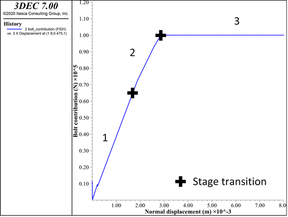
Figure 4: Hybrid bolt calibration. Typical pull test curves and associated stages.
Table 2 presents the critical parameters to adjust in order to obtain the desired behavior for hybrid bolts during a simple pull test.
| Stage | Primary Influence | Secondary Influence |
|---|---|---|
| Elastic stage (1) | young grout-stiffness |
|
| End of elastic stage | grout-cohesion |
|
| Yield stage (2) | grout-cohesion |
young |
| End of yield stage/Plastic stage (3) | yield-tension or grout-cohesion |
|
| End of plastic stage | tensile-failure-strain |
Below are a few comments to keep in mind while calibrating the hybrid bolt.
- Make sure the number of nodes and length of the cable is large enough that it does not influence the results of the calibration (i.e., ensure that the bolt length is long enough to fully exercise the bolt capacity and not get slip along the whole length of the bolt before reaching that stage).
- If the cable strain limit is very low compared to the dowel’s, then the rupture (axial and shear) will always be induced by cable (axial) rupture.
- The node spacing strongly influences the behavior of the bolt for a given joint displacement. The node spacing used for the calibration should be equal to the one used in the real problem.
Orientation-Dependent Shear Strength
In the field, rock bolts can be subjected to a combination and/or succession of shear and axial solicitation in various directions. Only a few references study the effect of bolt inclination on the bolt behavior when crossing a joint. The hybrid bolt model has not been implemented to reproduce all the complexity of rock bolt behavior in every possible condition. It is built to take into account the shear resistance generated by the bolt at joint intersections in a simple manner, while accurately reproducing the support brought to the rock mass observed experimentally. This section discusses the inclination effect on a simple shear test in 3DEC for a given set of parameters and compares it to observations available in the literature.
Laboratory tests suggest the following.
- The maximum shear strength of the bolted joint increases with the joint friction angle.
- For a given joint friction angle, the maximum shear strength of the bolted joint varies with the bolt inclination.
- Inclined bolts react in a stiffer way than normal ones.
- The greatest ultimate displacement is reached when the bolt is normal to the joint.
- For very low values of friction angle, the bolt inclination has no influence on the maximum resistance.
- The confining effect increases with inclination while the cohesion term decreases.
Figure 5 shows simple shear test results for a friction angle of 40º and various bolt inclinations (from 10º to 130º).
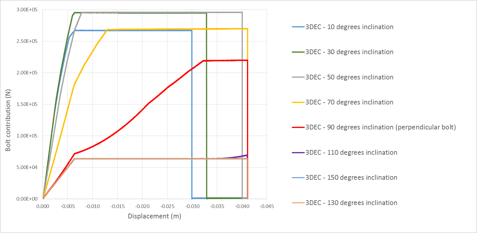
Figure 5: Bolt inclination effect on a simple shear test with a joint friction angle of 40º (inclination > 90º corresponds to bolt inclined in the opposite direction to the shearing direction).
Figure 6 shows simple pull test results for two inclination angles (from 70º to 90º).
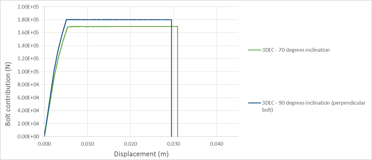
Figure 6: Bolt inclination effect on a pullout test.
Like the rock bolt behavior observed experimentally, the hybrid bolt behaves as follows.
- Inclined bolts react in a stiffer way than normal ones. This is due to a geometrical effect. Indeed, the more the bolt is inclined (compared to the perpendicular direction to the joint), the bigger the increment of axial force in the cable for a given increment of shear displacement.
- As the bolt rotates from the perpendicular direction, the confining effect (friction effect) increases while the cohesion term (dowel action and shear cable action) decreases.
- The ultimate shear displacement leading to bolt failure varies with bolt inclination. The ultimate shear displacement is maximum when the bolt is perpendicular to the joint. In this case, it is directly related to the input dowel shear rupture strain (maximum shear displacement = maximum dowel strain × dowel length). When the bolt is more inclined (\(\theta\) > 70 degrees in Figure 5), the cable strain limit for axial rupture is reached before the dowel strain limit since the cable element gets elongated more quickly. And the more the bolt is inclined, the less joint shear displacement is necessary for the cable to reach the axial strain limit.
Note that the inclination at which the rupture strain switches from being controlled by the dowel shear limit to being controlled by the cable axial limit depends on the input values. If the cable strain limit is very low compared to the dowel’s, then the rupture will always be induced by cable (axial) rupture. If the cable strain limit is infinite, then the controlling strain limit is always the dowel (shear) strain limit, independent of the orientation.
Shear tests have also been performed on bolts inclined in the opposite direction to shearing (inclination > 90° in Figure 5). In those cases, while the joint is sheared, the cable element gets compressed (and not stretched) so that the only force applied by the bolt on the joints comes from the dowel element. At the end of the elastic stage, when the dowel reaches its yield value, the force no longer increases except if the cable element rotates enough so that it gets stretched again (this is the case at the end of the test for \(\theta\) = 110°).
Figure 6 presents pullout test results for a bolt perpendicular to the joint and one slightly inclined (\(\theta\) = 70°). When the bolt is inclined, a given increment of displacement (when the block is pulled) induces a smaller stretch than when the bolt is perpendicular to the joint. That is why the stiffness is slightly lower. This is the same geometrical effect that causes the maximum axial displacement to be higher for the inclined bolt (~31 mm) than for the perpendicular bolt (~29 mm). When the bolt is perpendicular to the joint (and so parallel to the pulling direction), the maximum load equals the cable yield capacity (18 tonnes in this case). When the bolt is inclined, the maximum load equals the projection of this value on the pulling direction. The more inclined the bolt, the lower the maximum load when compared to the yield capacity of the bolt.
Very few experimental results are available that consider an inclined bolt subjected to shearing. In terms of qualitative behavior, the hybrid bolt reproduces most effects due to inclination described in the literature for analytical or experimental results. In terms of quantitative results, we believe the hybrid bolt behavior is reasonable considering the level of accuracy it is meant to achieve and in the order of magnitude observed in the few available experimental tests.
Effect of Joint Friction Angle on Bolt Load Capacity
During a simple shear test the three forces contributing to the bolt effect on the joint are the dowel element shear resistance (Fd), the cable shear resistance (FcS), and the additional friction force due to the cable normal force (FcN). If we consider a bolt inclination of \(\theta_1\) (so that 90º corresponds to a bolt perpendicular to the joint) and a joint friction angle of \(\phi\) degrees, the theoretical maximum bolt contribution equals:
where:
\(F_c\) = Axial force acting in the cable element whose maximum value is the input cable yield value;
\(F_d\) = Force acting in the dowel element whose maximum value is the input dowel yield value
The first term represents the shear resistance (FcS) and the second term represents the normal component (FcN).
As a consequence, the hybrid bolt contribution depends on the friction angle and the bolt inclination. Considering that the bolt rotates a few degrees during the simple shear test, Figure 7 gives an estimation of the three forces generated by the presence of the hybrid bolt for various bolt inclinations and for different friction angles.
Like the rock bolt behavior observed experimentally, the 3DEC hybrid bolt behaves as follows.
- For a given joint friction angle, the maximum shear strength of the bolted joint varies with the bolt inclination. For a 40 degree friction angle, the maximum value is observed around 45 degrees and corresponds to a 30% increase compared to a perpendicular bolt.
- The maximum shear strength of the bolted joint varies with the joint friction angle; the higher the friction, the higher the maximum shear strength.
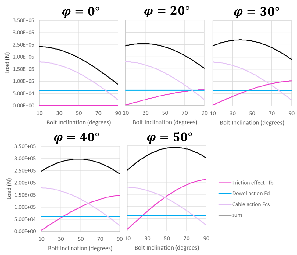
Figure 7: Variation of bolt action contributions with bolt inclination for five different joint friction angles (0º, 20º, 30º, 40º, and 50º) – a bolt inclination of 90º corresponds to a bolt perpendicular to the joint.
HTML Calibration Tool
A calibration tool for hybrid bolts is provided with this documentation to make it easier to choose bolt properties based on laboratory data. Default properties for different bolt types are also included with the tool. The tool provides its own documentation (see the “?” where it appears in the tool).
Example Applications
Simple examples are given to illustrate the use of hybrid bolts.
References
Dight, P. M. “Improvements to the Stability of Rock Walls in Open Pit Mines.” Ph.D. Thesis, Monash University (1982).
Fuller, P. G., and R. H. T. Cox. “Rock Reinforcement Design Based on Control of Joint Displacement — A New Concept,” in Proceedings of the 3rd Australian Tunnelling Conference (Sydney, Australia, 1978), pp. 28-35. Sydney: Inst. of Engrs., Australia (1978).
Gerdeen, J. C., et al. “Design Criteria for Roof Bolting Plans Using Fully Resin-Grouted Nontensioned Bolts to Reinforce Bedded Mine Roof,” U.S. Bureau of Mines, OFR 46(4)-80 (1977).
Hyett, A. J., W. F. Bawden and R. D. Reichert. “The Effect of Rock Mass Confinement on the Bond Strength of Fully Grouted Cable Bolts,” Int. J. Rock Mech. Min. Sci. & Geomech. Abstr., 29(5), 503-524 (1992).
Itasca Consulting Group Inc. UDEC (Universal Distinct Element Code), Version 5.0. Minneapolis: ICG (2011).
Littlejohn, G. S., and D. A. Bruce. “Rock Anchors – State of the Art. Part I: Design,” Ground Engineering, 8(3), 25-32 (1975).
Lorig, L. J. “A Simple Numerical Representation of Fully Bonded Passive Rock Reinforcement for Hard Rocks,” Computers and Geotechnics, 1, 79-97 (1985).
Pells, P. J. N. “The Behaviour of Fully Bonded Rock Bolts,” in Proceedings of the 3rd International Congress on Rock Mechanics, Vol. 2, pp. 1212-1217 (1974).
Commands & FISH
| Was this helpful? ... | FLAC3D © 2019, Itasca | Updated: Feb 25, 2024 |