Geogrid-Reinforced Embankment
Problem Statement
Note
To view this project in FLAC3D, use the menu command . Choose “Structure/Geogrid/ReinforcedEmbankment” and select “RinforcedEmbankment.prj” to load. The main data files used are shown at the end of this example. The remaining data files can be found in the project.
This example illustrates the behavior of a soil embankment reinforced with three geogrid layers. It is similar to the Soil Nailing example, wherein cables are used to reinforce the embankment. Three geogrids are installed at different levels in a vertical embankment. There is assumed to be no cohesive resistance between the geogrids and the soil. The friction angle of the geogrid-soil interface necessary to stabilize the embankment is determined.
The FLAC3D model consists of 48 geogrid elements and 121 zones, as shown in Figure 1. The model simulates a one-meter wide section of soil subjected to plane-strain conditions (no out-of-plane motion). During the construction of the actual embankment, the soil would have been added gradually with each geogrid layer being emplaced and then covered with soil. Instead, simply emplace all three geogrid layers into a stress-free soil, and then install the soil in-situ stresses that correspond with the soil weight. At this stage, each geogrid layer is subjected to a different confining stress that increases with depth. The embankment is now created by removing the constraint on the left side of the model and cycle until either equilibrium is reestablished or it becomes clear that the embankment is collapsing.
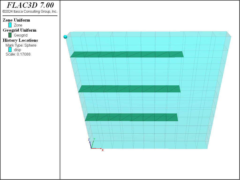
Figure 1: FLAC3D model for geogrid-reinforced embankment.
The soil is modeled as a Mohr-Coulomb material and assigned the same properties as in Soil Nailing. Geogrids in FLAC3D remain elastic; failure can occur in the geogrid-soil interface and/or in the soil zones. The geogrid is assigned the same properties as in Geogrid Pull-out Test (\(E\) = 26 GPa, \(\nu\) = 0.33, \(t\) = 5 mm, \(k\) = 2.3 N/m3, \(c\) = 0), and the friction angle is varied.
For a geogrid-soil interface friction angle of 0 degrees, the shear resistance of the geogrid is not mobilized, and the soil itself does not have sufficient strength to prevent the collapse of the embankment. Figure 2 shows that the geogrids are carrying no load, and that the slip condition has been reached at all geogrid nodes. A plot of the \(x\)-displacement of the top-left gridpoint (see Figure 3) indicates that the embankment is collapsing.
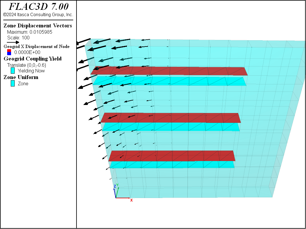
Figure 2: Tensile stress in geogrids with geogrid-soil interface friction angle of zero (the embankment is collapsing).
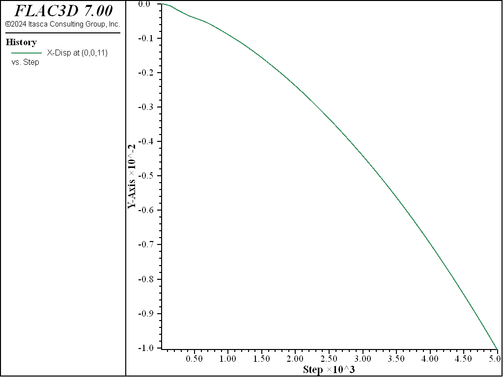
Figure 3: Total x-displacement of top-left gridpoint with geogrid-soil interface friction angle of zero (the embankment is collapsing).
By including a frictional resistance at the geogrid-soil interface of 5°, the geogrids are sufficient to stabilize the embankment (see Figure 4). Figure 5 plots the tensile stress in the geogrids for this case. The top geogrid layer has slipped and transferred load to the lower layers. The displacement field of the soil and the geogrids is shown in Figure 6. The counterclockwise rotation of the system and the decrease in pull-out deformation with depth are evident in this plot.
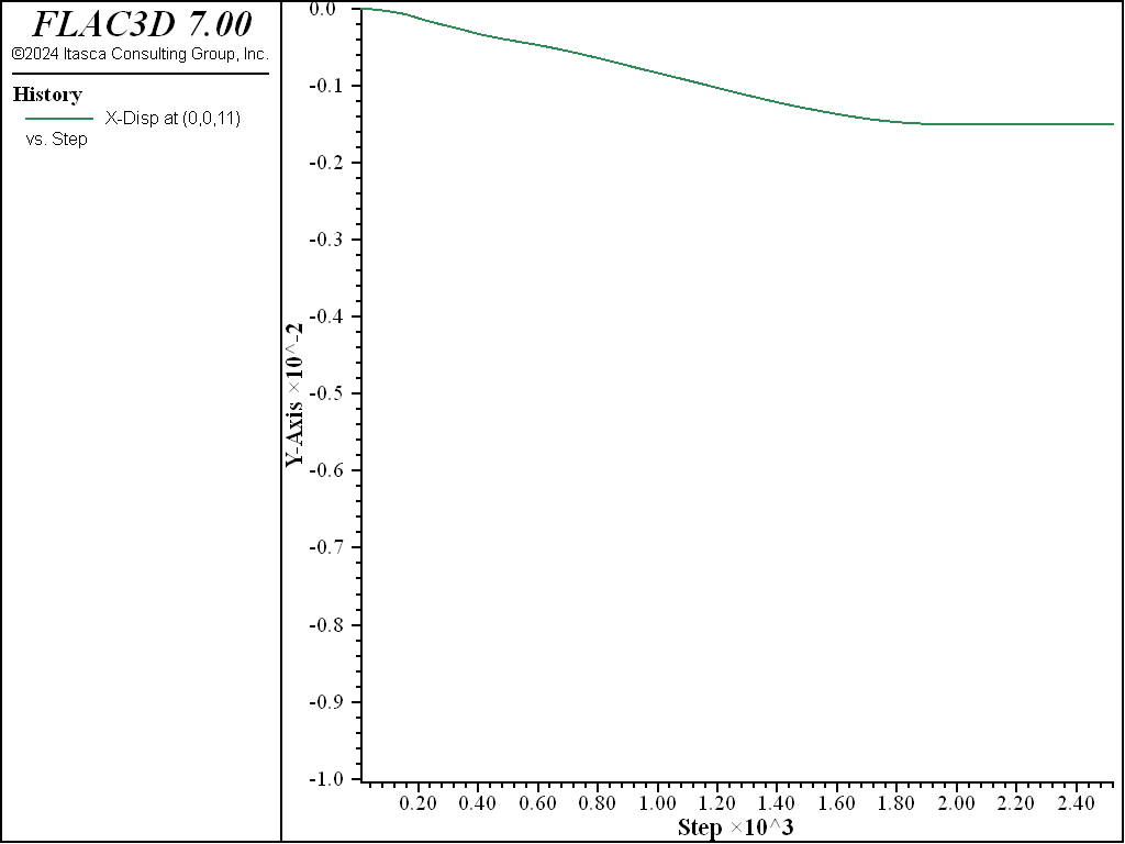
Figure 4: Total x-displacement of top-left gridpoint with geogrid-soil interface friction angle of 5° (the embankment is stable).
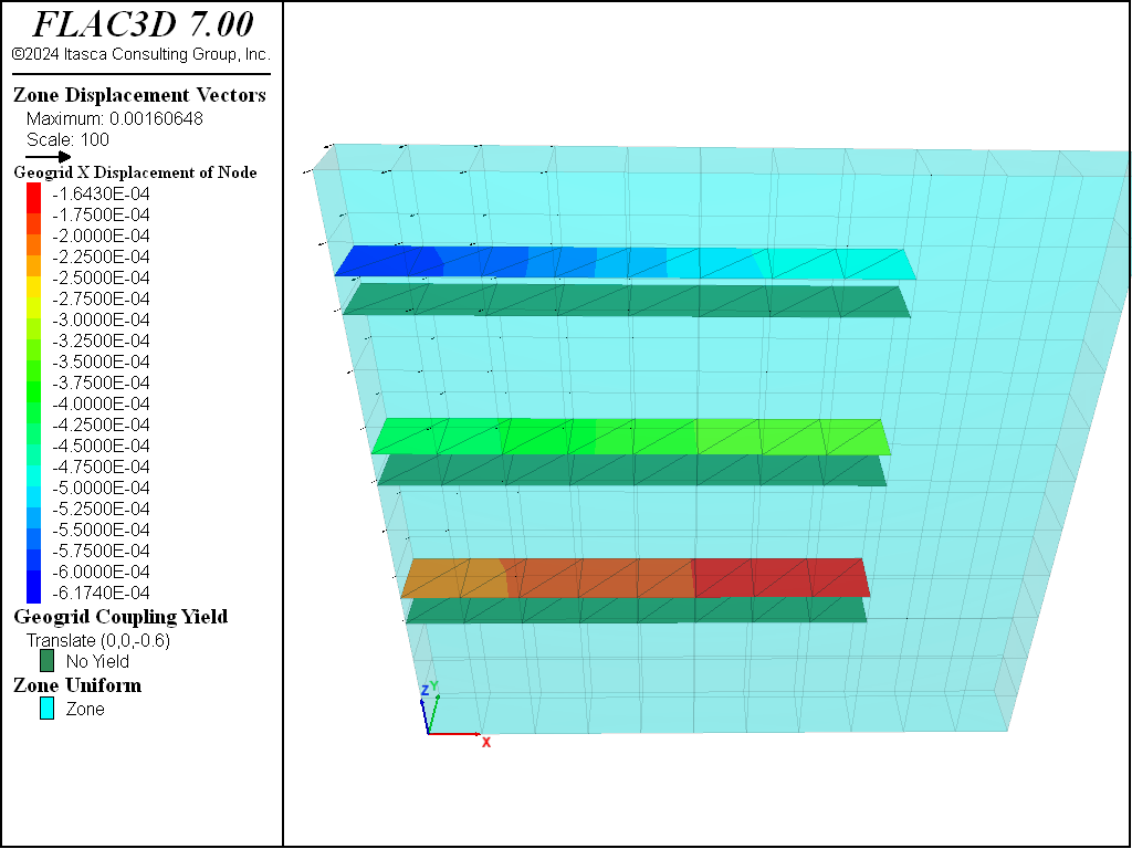
Figure 5: Tensile stress in geogrids with geogrid-soil interface friction angle of 5° (the embankment is stable).
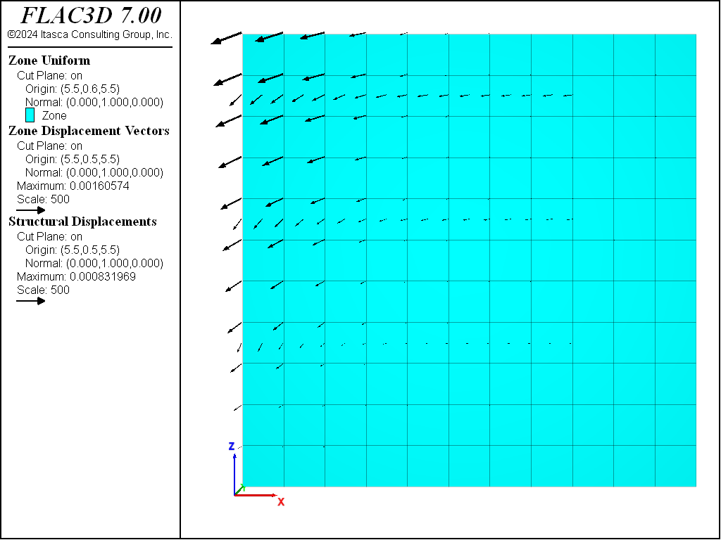
Figure 6: Displacement field in soil and geogrids with geogrid-soil interface friction angle of 5° (the embankment is stable).
Data File
ReinforcedEmbankment.dat
model new
model large-strain off
model title "Reinforced embankment (using geogrids)"
; Create soil and assign properties
zone create brick size 11 1 11
zone face skin ; Label zone boundaries
zone cmodel assign mohr-coulomb
zone property bulk 5e9 shear 1e9 cohesion 4e4 friction 30 density 2000
; Create three geogrid layers, and assign properties
struct geogrid create by-quadrilateral (0,0,9.5) (8,0,9.5) ...
                                       (8,1,9.5) (0,1,9.5) size (8,1)
struct geogrid create by-quadrilateral (0,0,6.5) (8,0,6.5) ...
                                       (8,1,6.5) (0,1,6.5) size (8,1)
struct geogrid create by-quadrilateral (0,0,3.5) (8,0,3.5) ...
                                       (8,1,3.5) (0,1,3.5) size (8,1)
struct geogrid property isotropic=(26e9, 0.33) thick=5e-3 ...
                        coupling-stiffness=2.3e6 coupling-cohesion=0.0 ...
                        coupling-friction=0 ; 0 coupling friction!
; Assign boundary conditions
zone face apply velocity-normal 0 range group 'East' or 'West'
zone face apply velocity-normal 0 range group 'North' or 'South'
zone face apply velocity (0,0,0) range group 'Bottom'
; Initial conditions
model gravity 10
zone initialize-stresses ratio 0.6,0.4
model solve convergence 1
; Histories
zone history name='disp' displacement-x position (0,0,11)
model save 'Initial'

; Case 1 - coupling friction 0
; Remove constraint on left side of model.
zone face apply-remove range group 'West'
; Solve, but stop after 5000 because we expect failure
model solve convergence 1 cycles 5000
model save 'Friction-0'

; Case 2 - coupling friction 5 degrees
model restore 'Initial'
struct geogrid property coupling-friction=5
model solve convergence 1
; Remove constraint on left side of model.
zone face apply-remove range group 'West'
; Solve
model solve convergence 1
model save 'Friction-5'
| Was this helpful? ... | FLAC3D © 2019, Itasca | Updated: Feb 25, 2024 |