wall export command
Syntax
- wall export keyword <range>
Primary keywords:
Exports walls. If no range is specified, then all walls in the model are exported. At the moment, it is only possible to export walls to geometry sets.
- geometry keyword
- set s
Set the geometry set base name to s. If the
splitkeyword is specified, then each wall is exported into a dedicated geometry set with a name corresponding to the base name to which the word wall followed by the wall ID is appended (e.g., ‘myset_wall1’ for a base name myset and the wall with ID 1). Note that in this case, existing sets with the same name are overridden. Otherwise all walls are exported into one unique geometry set with name s, and existing geometry objects in this set are not deleted. The default geometry set base name is walls.
- split
If specified, the split keyword results in each wall being exported into a dedicated geometry set. By default, all the walls are exported into one unique geometry set (see above).
Usage Examples
The wall export command can be used to export wall geometries into geometry sets. The geometry sets may in turn be directly used for post-processing or exported as STL files to be used by a third-party CAD software. Detailed information about the geometry logic can be found here.
The following example creates three walls and executes the wall export geometry command with its default parameters. The walls are exported into one unique geometry set labeled walls, shown in Figure 1.
model domain extent -10 10
wall generate sphere position 0.0 0.0 5.0 radius 2.5
wall generate cone base -2.5 0.0 -5.0 axis 1 1 1 height 2.0 radius 0.1 2.5 ...
                   cap true true  resolution 0.5 one-wall
wall generate disk radius 5.0 dip 45.0 dip-direction 90.0

wall export geometry
geometry export 'walls.stl' format stl
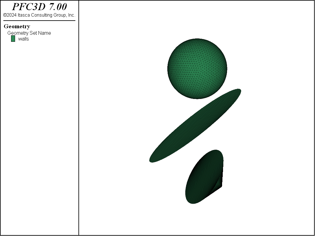
Figure 1: Using default parameters, the wall export geometry command exports wall geometries into one
unique geometry set labeled walls.
The default parameters may be overridden to control the outcome of the command. The example below constructs the same model as above, but the split keyword is used to automatically export each wall into a dedicated geometry set. Each set may then be exported as an STL file with the geometry export command.
model domain extent -10 10
wall generate sphere position 0.0 0.0 5.0 radius 2.5
wall generate cone base -2.5 0.0 -5.0 axis 1 1 1 height 2.0 radius 0.1 2.5 ...
                   cap true true  resolution 0.5 one-wall
wall generate disk radius 5.0 dip 45.0 dip-direction 90.0

wall export geometry split
geometry set 'walls_wall1'
geometry export 'wall1.stl' format stl
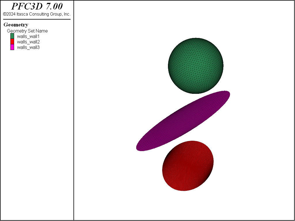
Figure 2: In this example, the use of the split keyword results in each wall being exported into a dedicated geometry set.
See also
| Was this helpful? ... | FLAC3D © 2019, Itasca | Updated: Feb 25, 2024 |