Example: FOS Calculations Using the Strength Reduction Method
Failure Modes of a Simple Slope in Jointed Mohr-Coulomb Material
Note
To view this project in 3DEC, use the menu command . Choose “3DEC/ TheoryAndBackground/ Factor_of_SafetyMC_Slope” and select “mcslope.prj” to load. The data files used are shown at the end of this example.
Factor-of-safety calculations using the strength reduction method in 3DEC can determine both the safety factor and the mode of failure of a slope in a jointed rock mass. Several models are run in this section to illustrate the different types of failure modes that can be identified from a factor-of-safety calculation. Modes of failure include rock mass failure in a homogeneous and unjointed rock slope, plane failure of slopes containing either daylighting or non-daylighting discontinuities, and block and flexural toppling failure involving either forward or backward toppling of blocks. (These slope models and modes of failure are also described in detail by Lorig and Varona [2004].)
The jointed rock failure modes presented in this section assume the joint structure can be represented as a system of discrete blocks. Failure modes involving joints that terminate within intact rock, such as step-path failure, can also be simulated with 3DEC.
A simple slope geometry is used for all of the stability analysis cases described in this section. The slope has a height of 260 m and slope angle of 55°. The rock blocks in the model are represented as deformable Mohr-Coulomb material, and the discontinuities behave as Coulomb joint material. A maximum zone size of 5 m is assigned for the deformable blocks in all models. The model slope geometry used for all cases is shown below.

Figure 1: Slope geometry.
Six slope stability cases are analyzed. The cases include one model with no joint structure, three models with one joint set, and two models with two joint sets. The rock block properties and joint properties for the six cases are listed in Table 1.
Soil Property |
Case 1 |
Case 2 |
Case 3 |
Case 4 |
Case 5 |
Case 6 |
|---|---|---|---|---|---|---|
Rock Density (kg/m3) |
2660 |
2660 |
2660 |
2660 |
2660 |
2660 |
Rock Bulk Modulus (GPa) |
6.3 |
6.3 |
6.3 |
6.3 |
6.3 |
6.3 |
Rock Shear Modulus (GPa) |
3.6 |
3.6 |
3.6 |
3.6 |
3.6 |
3.6 |
Rock Cohesion (kPa) |
675 |
675 |
675 |
675 |
675 |
1010 |
Rock Tension (kPa) |
0 |
0 |
0 |
0 |
0 |
1010 |
Rock Friction (degrees) |
43 |
43 |
43 |
43 |
43 |
43 |
Joint Set 1 Dip (degrees) |
– |
145 |
110 |
70 |
70 |
125 |
Joint Set 1 Spacing (m) |
– |
10 |
20 |
20 |
20 |
10 |
Joint Set 1 Friction (degrees) |
– |
40 |
40 |
40 |
40 |
40 |
Joint Set 1 Cohesion (kPa) |
– |
100 |
0 |
0 |
0 |
0 |
Joint Set 1 Stiffness (GPa/m) |
– |
1 |
1 |
1 |
1 |
1 |
Joint Set 2 Dip (degrees) |
– |
– |
– |
– |
340 |
0 |
Joint Set 2 Spacing (m) |
– |
– |
– |
– |
30 |
40 |
Joint Set 2 Friction (degrees) |
– |
– |
– |
– |
40 |
40 |
Joint Set 2 Cohesion (kPa) |
– |
– |
– |
– |
0 |
0 |
Joint Set 2 Stiffness (GPa/m) |
– |
– |
– |
– |
1 |
1 |
The cases illustrate six different failure conditions. They are discussed separately in the following pages. The command listing for the six cases is given below.
Case 1: Unjointed, homogeneous rock – rock mass failure
For Case 1, the slope is a homogeneous rock without joints. Failure of the slope primarily involves shearing though the rock mass, and the shear failure surface is approximately circular as shown in Figure 2. For the Case 1 rock properties listed in Table 1, a factor of safety of 1.68 is calculated. Note that the failure surface in a 3DEC model can usually be most clearly identified from a plot of velocity vectors, and either a displacement or velocity contour plot. In Figure 2 velocity vectors and \(x\)-velocity contours clearly show the failure surface:
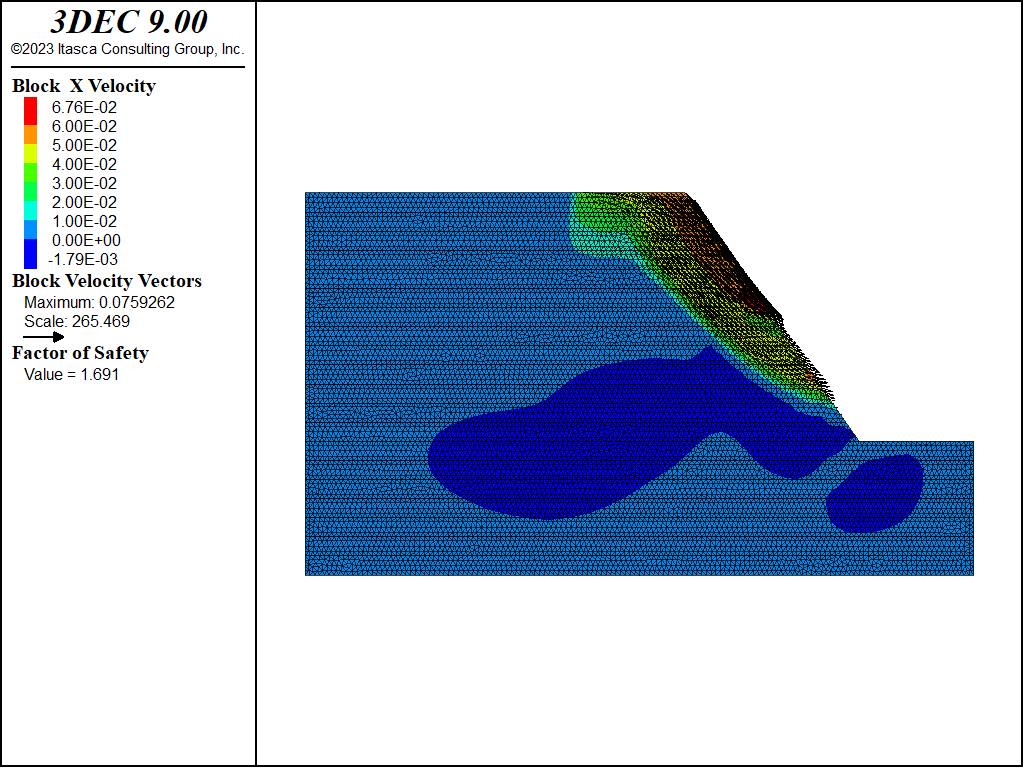
Figure 2: Case 1 — rock mass failure.
Case 2: Daylighting joint structure — plane failure
In the Case 2 simulation, a single joint set is added to the model. The joints dip at 145° (i.e., daylighting out of the slope at 35°) and are spaced at 20 m. The failure mechanism that develops combines sliding along joints near the slope toe with tensile failure of the blocks near the top of the slope. Figure 3 shows the failure surface. The calculated factor of safety is 1.31 for this case.
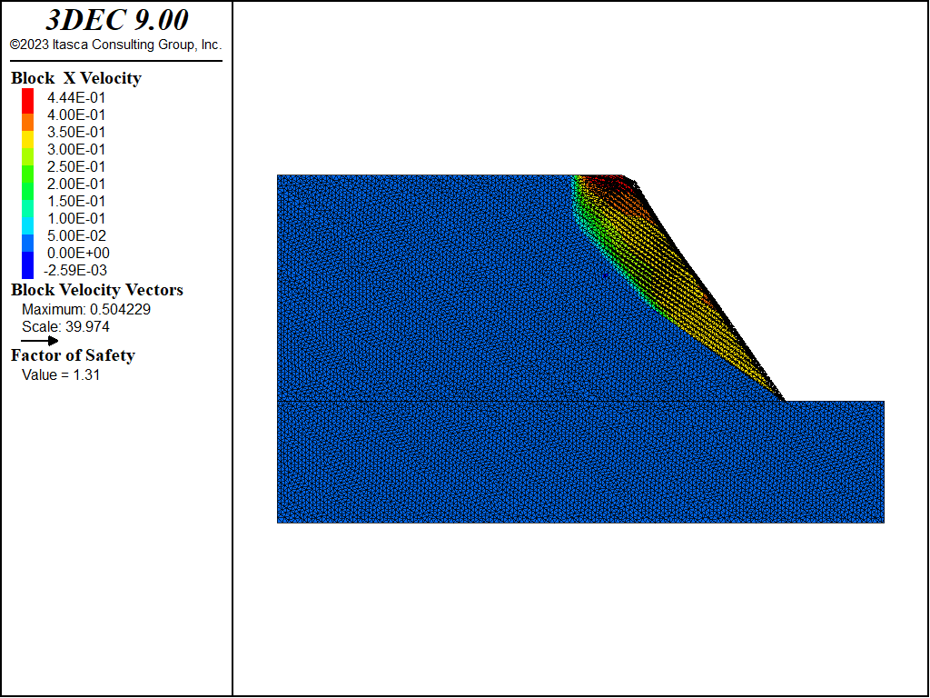
Figure 3: Case 2 — plane failure in slope with daylighting joints.
Case 3: Non-daylighting joint structure — plane failure
In the third case, the dip angle of the single joint set is set to 110° (or 70° in the same direction as the slope). This produces non-daylighting joints along the slope face. The joint spacing is 20 m. The failure mode that develops in this case involves sliding along the discontinuities, and shearing through the rock blocks at the toe of the slope. Figure 4 illustrates the failure mechanism. The resulting factor of safety is 1.54 for the given problem conditions.
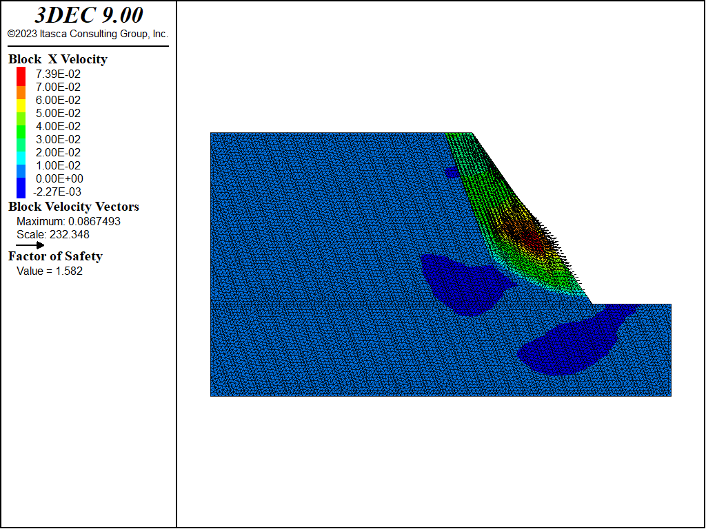
Figure 4: Case 3 — plane failure in slope with non-daylighting joints.
Case 4: Joints dipping into the slope — flexural toppling failure
The joint set is oriented at a dip angle of 70° and spaced at 20 m, in Case 4. This results in joints dipping steeply into the slope face. The joints form columns that tend to bend out of the slope, and result in a flexural toppling failure mode. Figure 5 shows the failure surface, and Figure 6 illustrates the flexural toppling mode from a magnified view of the block deformation. The calculated factor of safety is 1.26.
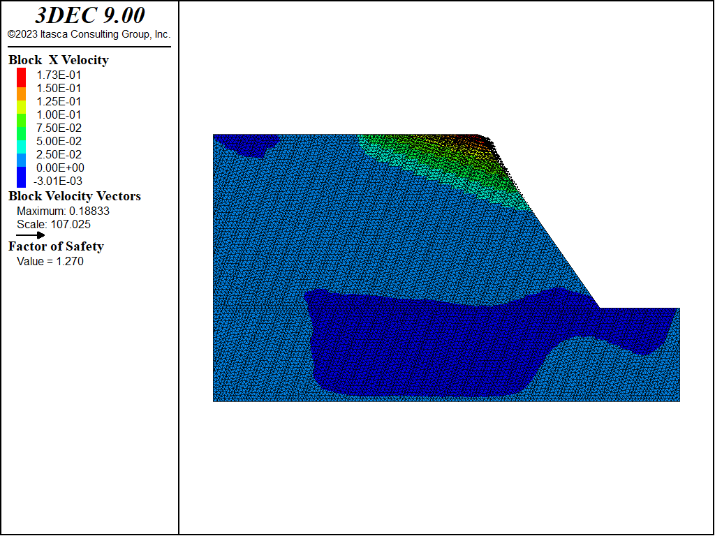
Figure 5: Case 4 — flexural toppling failure for joints dipping into the slope.
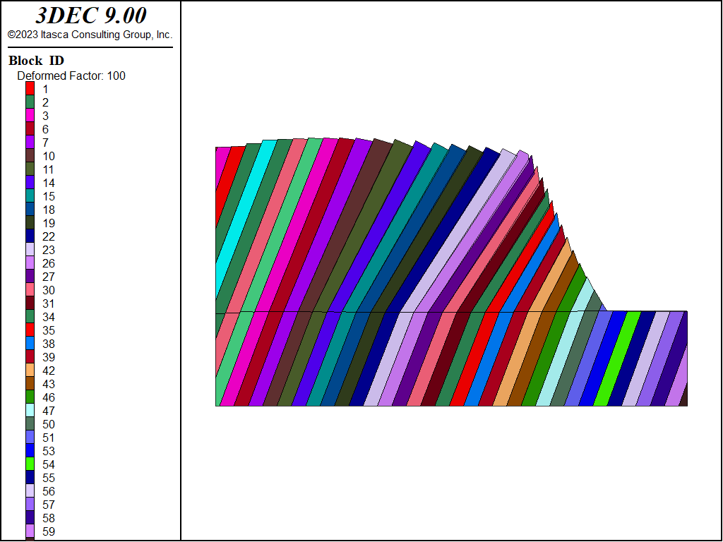
Figure 6: Case 4 — flexural toppling mode identified from magnified block deformation.
Case 5: Two orthogonal joint sets — forward block toppling failure
The slope contains two orthogonal joint sets, in Case 5. One set dips at 70° with a spacing of 20 m, and a cross-joint set dips at −20° with a spacing of 30 m. The cross-joints provide release surfaces for rotation of the blocks. The blocks, driven by self-weight, rotate forward out of the slope. Figure 7 shows the failure surface for the Case 5 conditions. The calculated factor of safety is 1.11. The magnified block deformation plot in Figure 8 illustrates the forward block rotation out of the slope.
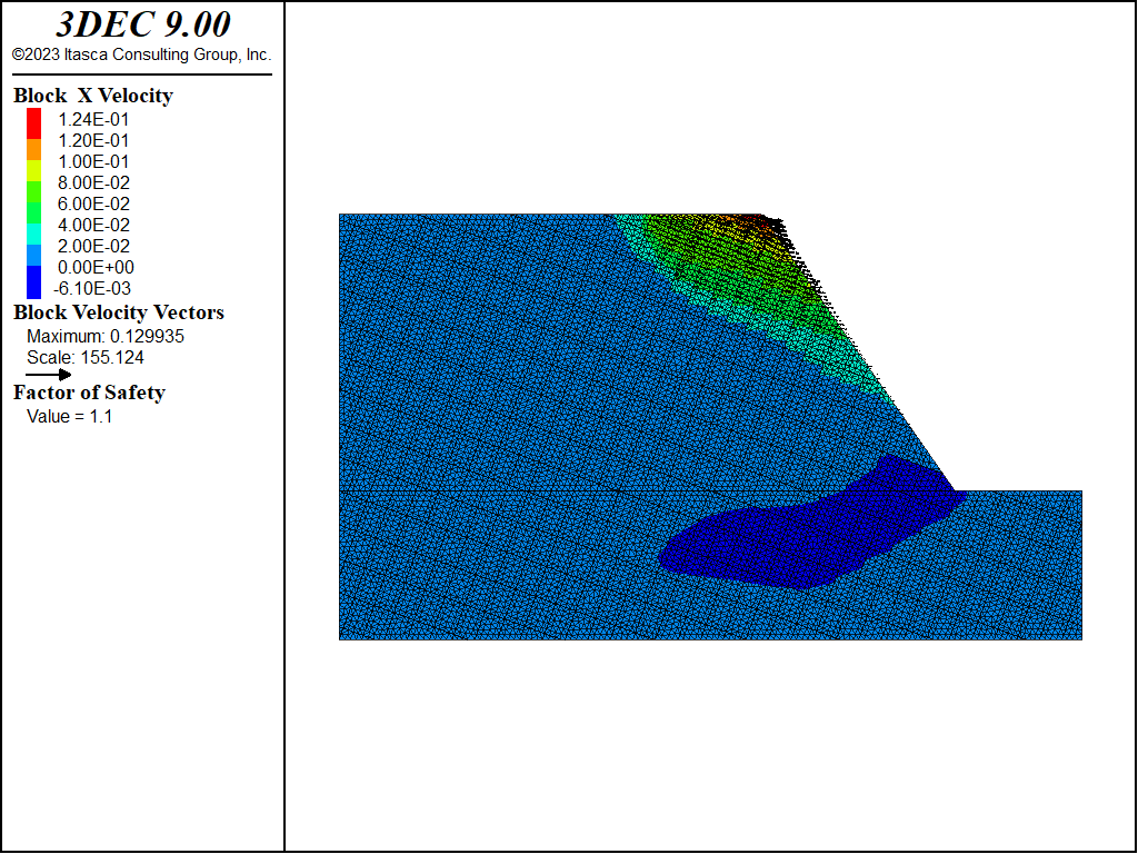
Figure 7: Case 5 — forward block toppling failure for a slope with two joint sets.
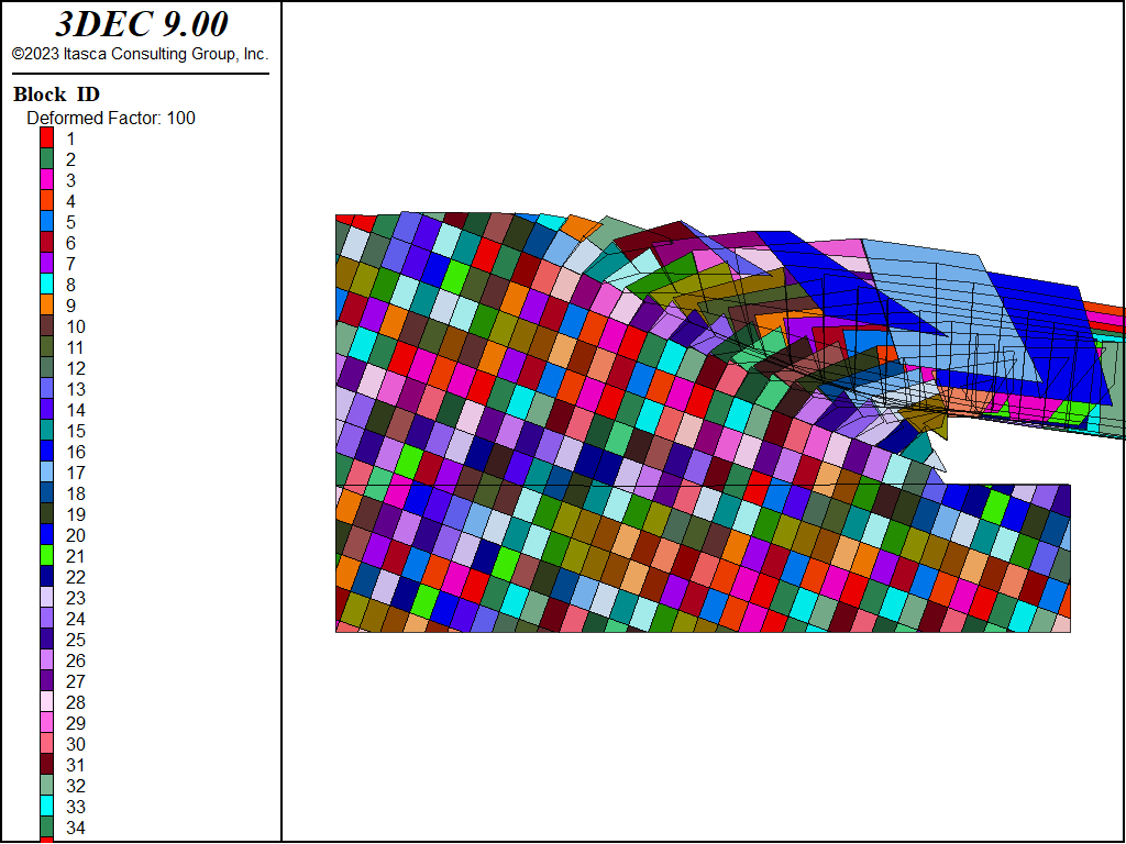
Figure 8: Case 5 — forward block toppling mode identified from magnified block deformation.
Case 6: Two orthogonal joint sets — reverse (backward) block toppling failure
Backward or reverse block toppling failure of a slope can occur when joints parallel to the slope face and flatter cross-joints are particularly weak. In Case 6, one joint set is oriented at 125° (i.e., parallel to the slope face) with a spacing of 10 m. A cross-joint set is horizontal and spaced at 40 m. Note that in this case, in order to highlight the failure mode, elastic material behavior is prescribed for the rock blocks. Figure 9 displays the reverse toppling failure mode. The calculated factor of safety is 1.85. The backward block toppling mode is clearly seen in the magnified block deformation plot in Figure 10.
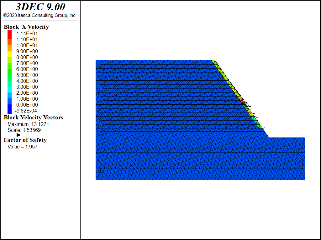
Figure 9: Case 6 — reverse block toppling failure for a slope with two joint sets.
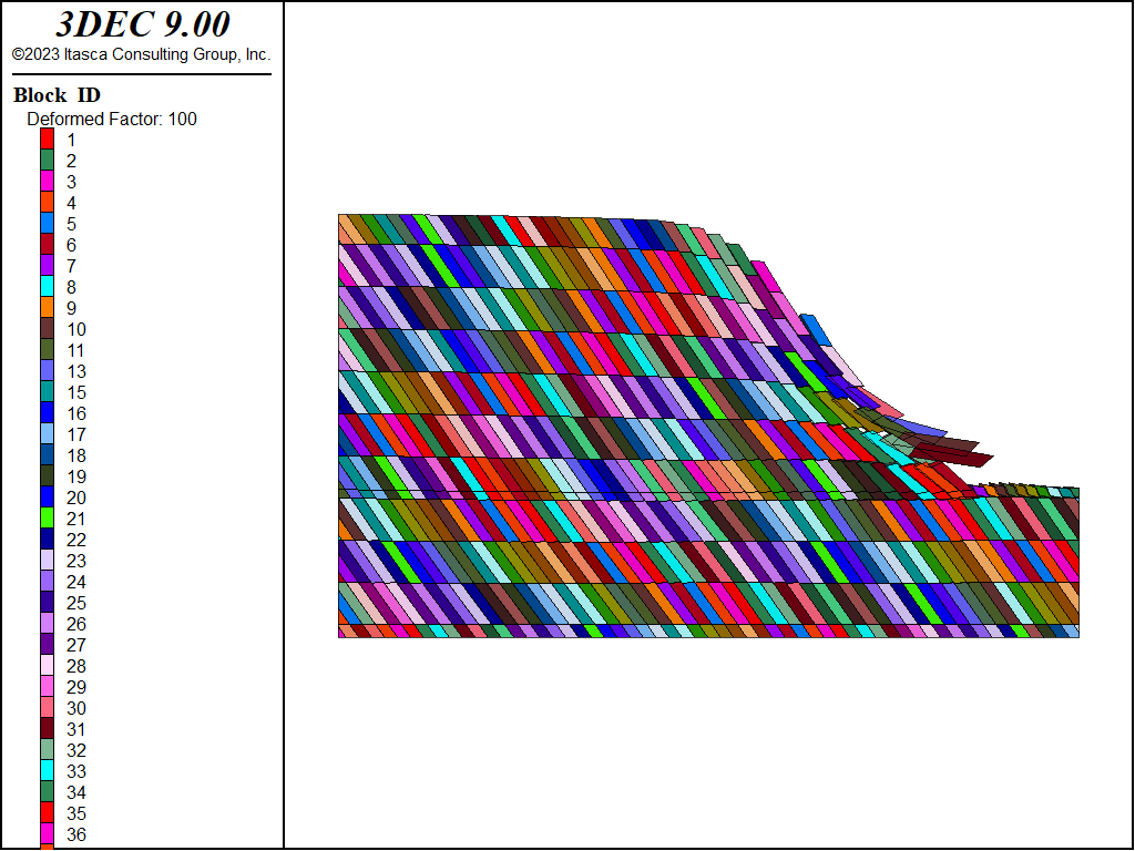
Figure 10: Case 6 — reverse block toppling mode identified from magnified block deformation.
Data Files
mcslope-rockmass.dat
model new
model large-strain off

; File: mcslope.dat
; Failure Modes of a Simple Slope
;
; Case 1
; Rock Mass Failure
;
block create prism face-1 0 0 140 0 0 400 398 0 400 580 0 140 ...
  face-2 0 5 140 0 5 400 398 5 400 580 5 140
block create brick 0 700 0 5 0 140
block cut joint-set dip 0 dip-direction 0 spac 20 num 140 origin 0,0,0
block join
block zone generate edgelength 5

block zone cmodel assign mohr-coulomb
block zone property density 2.66E3 bulk 6.3E9 shear 3.6E9 ...
  friction 43 cohesion 6.75E5

block gridpoint apply velocity-x 0 range position-x 0
block gridpoint apply velocity-x 0 range position-x 700
block gridpoint apply velocity-y 0 range position-y 0
block gridpoint apply velocity-y 0 range position-y 5
block gridpoint apply velocity-x 0 range position-z 0
block gridpoint apply velocity-y 0 range position-z 0
block gridpoint apply velocity-z 0 range position-z 0

model gravity 0.0 0.0 -9.81
;
block zone nodal-mixed-discretization on
model solve elastic ratio 1e-6

block gridpoint initialize velocity 0 0 0
block gridpoint initialize displacement 0 0 0

model factor-of-safety filename 'rockmass'
mcslope-daylight.dat
model new
model large-strain off
;
; Case 2
; Plane Failure in Slope
;
block create prism face-1 0 0 140 0 0 400 398 0 400 580 0 140 ...
  face-2 0 5 140 01 5 400 398 5 400 580 5 140
block create brick 0 700 0 5 0 140
block join
block cut joint-set dip 35 dip-direction 90 spacing 10 num 140 origin 0,0,0

block zone generate edgelength 5

block zone cmodel assign mohr-coulomb
block zone property density 2.66E3 bulk 6.3E9 shear 3.6E9 ...
  friction 43 cohesion 6.75E5 ;

block contact jmodel assign mohr
block contact property stiffness-shear 1E9 stiffness-normal 1E9 ...
  friction 40 cohesion 1E5 cohesion-residuial 1e5

block gridpoint apply velocity-x 0 range position-x 0
block gridpoint apply velocity-x 0 range position-x 700
block gridpoint apply velocity-y 0 range position-y 0
block gridpoint apply velocity-y 0 range position-y 5
block gridpoint apply velocity-x 0 range position-z 0
block gridpoint apply velocity-y 0 range position-z 0
block gridpoint apply velocity-z 0 range position-z 0

model gravity 0.0 0.0 -9.81
;
block zone nodal-mixed-discretization on
model solve elastic
model save 'plane-ini'
block gridpoint initialize velocity 0 0 0
block gridpoint initialize displacement 0 0 0

model factor-of-safety filename 'daylight'
mcslope-nodaylight.dat
model new
model large-strain off
;
; Case 3
; Plane Failure in Slope - Non-Daylighting Joints
;
block create prism face-1 0 0 140 0 0 400 398 0 400 580 0 140 ...
  face-2 0 5 140 0 5 400 398 5 400 580 5 140
block create brick 0 700 0 5 0 140
block join
block cut joint-set dip 70 dip-direction 90 spacing 20 num 70 origin 12,0,0

block zone generate edgelength 5

block zone cmodel assign mohr-coulomb
block zone property density 2.66E3 bulk 6.3E9 shear 3.6E9 ...
  friction 43 cohesion 6.75E5

block contact jmodel assign mohr
block contact property stiffness-shear 1E9 stiffness-normal 1E9 ...
  friction 40 cohesion 0.0

block gridpoint apply velocity-x 0 range position-x 0
block gridpoint apply velocity-x 0 range position-x 700
block gridpoint apply velocity-y 0 range position-y 0
block gridpoint apply velocity-y 0 range position-y 5
block gridpoint apply velocity-x 0 range position-z 0
block gridpoint apply velocity-y 0 range position-z 0
block gridpoint apply velocity-z 0 range position-z 0

model gravity 0.0 0.0 -9.81
;
block zone nodal-mixed-discretization on
model solve elastic ratio 1e-6

block gridpoint initialize velocity 0 0 0
block gridpoint initialize displacement 0 0 0

model factor-of-safety filename 'nodaylight'
mcslope-flexuraltopple.dat
model new
model large-strain off
;
; Case 4
; Flexural Toppling
;
block create prism face-1 0 0 140 0 0 400 398 0 400 580 0 140 ...
  face-2 0 5 140 0 5 400 398 5 400 580 5 140
block create brick 0 700 0 5 0 140

block join
block cut joint-set dip 70 dip-direction 270 spacing 20 num 70 origin 6,0,0

block zone generate edgelength 5
block zone cmodel assign mohr-coulomb
block zone property density 2.66E3 bulk 6.3E9 shear 3.6E9 ...
  friction 43 cohesion 6.75E5

block contact jmodel assign mohr
block contact property stiffness-shear 1E9 stiffness-normal 1E9 ...
  friction 40 cohesion 0.0

block gridpoint apply velocity-x 0 range position-x 0
block gridpoint apply velocity-x 0 range position-x 700
block gridpoint apply velocity-y 0 range position-y 0
block gridpoint apply velocity-y 0 range position-y 5
block gridpoint apply velocity-x 0 range position-z 0
block gridpoint apply velocity-y 0 range position-z 0
block gridpoint apply velocity-z 0 range position-z 0

model gravity 0.0 0.0 -9.81
;

block zone nodal-mixed-discretization on
model solve elastic ratio 1e-6

block gridpoint initialize velocity 0 0 0
block gridpoint initialize displacement 0 0 0

model factor-of-safety filename 'flexural-topple'
mcslope-forwardtopple.dat
model new
model large-strain off

;
; Case 5
; Forward Toppling
;
block create prism face-1 0 0 140 0 0 400 398 0 400 580 0 140 ...
  face-2 0 5 140 0 5 400 398 5 400 580 5 140
block create brick 0 700 0 5 0 140
block join
block cut joint-set dip 70 dip-direction 270 spacing 20 num 70 origin 0,0,0
block cut joint-set dip 20 dip-direction 90  spacing 30 num 70 origin 0,0,12

block zone generate edgelength 5
block zone cmodel assign mohr-coulomb
block zone property density 2.66E3 bulk 6.3E9 shear 3.6E9 ...
  friction 43 cohesion 6.75E5

block contact jmodel assign mohr
block contact property stiffness-shear 1E9 stiffness-normal 1E9 ...
  friction 40 cohesion 0.0

block gridpoint apply velocity-x 0 range position-x 0
block gridpoint apply velocity-x 0 range position-x 700
block gridpoint apply velocity-y 0 range position-y 0
block gridpoint apply velocity-y 0 range position-y 5
block gridpoint apply velocity-x 0 range position-z 0
block gridpoint apply velocity-y 0 range position-z 0
block gridpoint apply velocity-z 0 range position-z 0

model gravity 0.0 0.0 -9.81
;

block zone nodal-mixed-discretization on
model solve elastic ratio 1e-6

block gridpoint initialize velocity 0 0 0
block gridpoint initialize displacement 0 0 0

model factor-of-safety filename 'forward-topple'
mcslope-reversetopple.dat
model new
model large-strain off
;
; Case 6
; Reverse Toppling
;
block create prism face-1 0 0 140 0 0 400 398 0 400 580 0 140 ...
  face-2 0 15 140 0 15 400 398 15 400 580 15 140
block create brick 0 700 0 15 0 140

block join
block cut joint-set dip 55 dip-direction 90 spacing 10 num 170 origin 7,0,0
block cut joint-set dip  0 dip-direction  0 spacing 40 num 70 origin 0,0,12

block zone generate edgelength 15
; needs to be mohr-coulomb forigin FOS
block zone cmodel assign mohr-coulomb
block zone property density 2.66E3 bulk 6.3E9 shear 3.6E9 ...
  cohesion 1e12 tension 1e12

block contact jmodel assign mohr
block contact property stiffness-shear 1E9 stiffness-normal 1E9 ...
  friction 40 cohesion 0.0

block gridpoint apply velocity-x 0 range position-x 0
block gridpoint apply velocity-x 0 range position-x 700
block gridpoint apply velocity-y 0 range position-y 0
block gridpoint apply velocity-y 0 range position-y 15
block gridpoint apply velocity-x 0 range position-z 0
block gridpoint apply velocity-y 0 range position-z 0
block gridpoint apply velocity-z 0 range position-z 0

model gravity 0.0 0.0 -9.81
;
block zone nodal-mixed-discretization on
model solve elastic ratio 1e-6

block gridpoint initialize velocity 0 0 0
block gridpoint initialize displacement 0 0 0

model factor-of-safety filename 'reverse-topple'
⇐ Example Factor of Safety Calculations using the Strength Reduction Method | Verification: Tests for a Simple Slope in Hoek-Brown Material ⇒
| Was this helpful? ... | Itasca Software © 2024, Itasca | Updated: Apr 02, 2024 |
