Assessment of Fault Slip Potential from Sill Pillar Mining
Problem Statement
Note
The project file for this example may be viewed/run in 3DEC.[1] The data files used are shown at the end of this example.
A 10-meter thick vertically dipping orebody is being mined by cut-and-fill methods at a depth of 950 to 1050 meters. Mining has taken place on two different levels, resulting in the formation of a sill pillar. The plan is to mine the sill pillar from the base up, in four cut-and-fill stages. Two vertical faults intersect the sill pillar, and it is necessary to determine the potential for slip on these features as mining of the sill pillar proceeds. Figure 1 shows the shape of the orebody in plan and long section, along with the locations of the faults, and the magnitude and the orientation of the in-situ stresses.
The properties of the ore, host rock and fill are outlined:
ore |
host rock |
backfill |
|
density (kg/m3) |
2700 |
2700 |
2000 |
bulk modulus (GPa) |
17.6 |
3.2 |
0.03 |
shear modulus (GPa) |
13.2 |
9.9 |
0.014 |
cohesion (MPa) |
10 |
8 |
0.05 |
friction angle (degrees) |
43 |
43 |
40 |
The properties of the faults are:
normal stiffness (N/m): 1 × 10¹¹
shear stiffness (N/m): 1 × 10¹¹
cohesion (MPa): 0
friction angle (degrees): 30
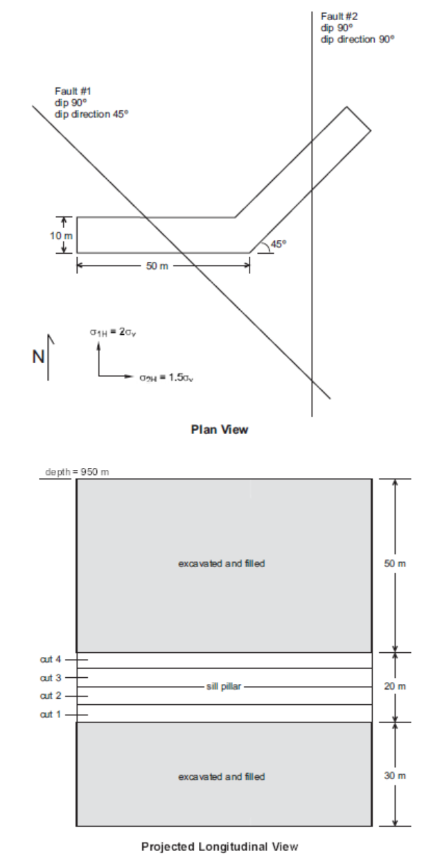
Figure 1: Diagram of the orebody, sill pillar, and faults.
Modeling Procedure
The model is generated with the file “SEIS.DAT”. The first step in building the model is to define the horizontal limits of the orebody by using the block cut joint-set, block hide, and block hide off commands to cut up the model block into smaller blocks. After defining each arm of the orebody independently, the orebody as a whole (running the full vertical height of the model) is marked as a separate region from the host rock. The vertical limits of the lower stope, upper stope and sill pillar cuts are then defined and marked as separate regions by hiding the entire model except the orebody, and creating individual horizontal cuts with the block cut joint-set command. The individual stopes and cuts are marked as separate regions by using the block hide, block hide off, and block group commands. Figure 2 is a perspective plot of the upper and lower stopes in the 3DEC model.
Once the orebody and stopes are defined, the two faults are cut and the model is divided into inner, middle and outer regions for zoning purposes. Any cuts in the model must be made before zoning occurs. The inner region, corresponding to the volume surrounding the orebody, is zoned with constant-strain elements with a 5-meter edge length. The middle and outer regions are zoned with 20- and 80-meter edge length zones, respectively. After zoning the model, all of the blocks surrounding the faults are joined since they are only an artifact of the model construction process and do not represent actual discontinuities in the rock mass.
In the model, the host rock, ore and fill are all assumed to behave as Mohr-Coulomb materials. The faults are assumed to behave according to the default joint constitutive model, which involves point area contact and elastic/plastic behavior with Coulomb slip failure. All of the model boundaries are pinned by applying a zero-velocity boundary condition in all coordinate directions using the block gridpoint apply command. In-situ stresses are applied to the model to match the gravitational gradient.
After the model has been brought to an initial equilibrium state, the upper and lower stopes are excavated using the block excavate command, and the model is run to equilibrium. These stopes are then filled, and the sill pillar cuts are excavated and filled in sequence. The block fill command is used to fill stopes. As part of this command, the constitutive models and properties for the blocks and joints making up the fill may be changed from the original material. For this model, the properties are changed to that of the fill, while the joint is glued (jmodel elastic). This prevents slip from occurring on the faults where they pass through the fill. Following excavation of each cut, the model is run to equilibrium before filling, to simulate the delay in filling that occurs in reality. Following mining of the upper and lower stopes, and after each sill pillar cut, the displacements on the faults are reset to zero so that the influence of each mining step on the faults may be determined. This does not affect the solution in any way, since velocities, rather than displacements, are used in the solution process. The displacements are calculated for the convenience of the user.
The model contains 65,383 zones and requires 13 MB of RAM.
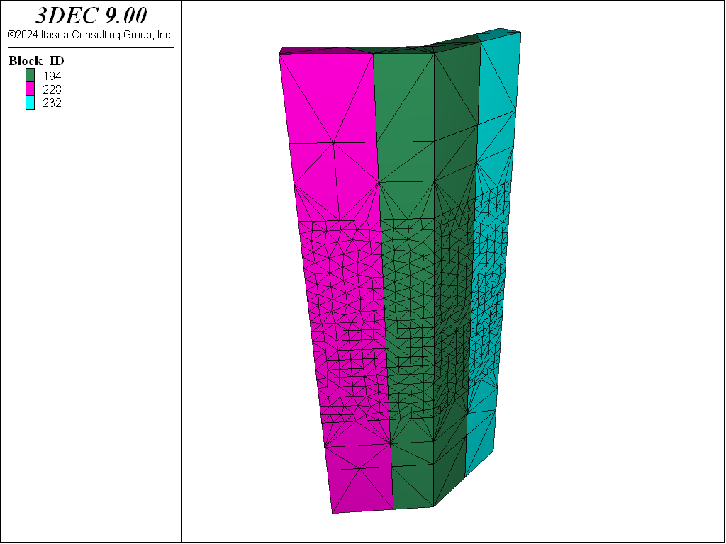
Figure 2: Perspective plot of the upper and lower stopes in the 3DEC model.
Results
Figures 3 and 4 show the predicted shear displacements and area of slip on Fault #1 and Fault #2, following mining of the upper and lower stopes. The view of the surface of Fault #1 is from the southwest, and the view of the surface of Fault #2 is from the east. Areas on the fault that have slipped are indicated by a hollow circle, and the shear displacement is contoured. As seen, areas of slip and shear displacement are predicted on the faults where they intersect both sides of the two excavated stopes. This is expected, since the blocks of rock are much freer to move relative to one another at the excavation boundary. The maximum shear displacement of 1.5 cm occurs where Fault #2 intersects the upper stope. In the 3DEC model, the upper and lower stopes are excavated in a single step, then filled. In reality, the stopes were excavated and filled in an incremental fashion. So the shear displacement predicted for this stage would be expected to occur incrementally as mining progressed. The sill cut, however, is excavated and filled in an incremental fashion in the model as well, so that displacements can be determined as a function of mining step.
Figures 5 and 10 show the predicted shear displacements and area of slip on both faults for the four sill pillar cuts. For the first 2 cuts (Figures 5 to 8), shear displacements are very small (2-8 mm) and are limited to the areas on the faults adjacent to the current cut. On the third cut (Figures 9 and 10), slip and shear displacement also occur in the ore between the current cut and the bottom of the upper stope. Shear displacements are on the order of 1 cm, but the area of slip is less than 50 m2. When the fourth and final cut is taken (Figures 11 and 12), a very large area of slip (approximately 1850 m2 in size), with a maximum shear displacement of 2.4 cm, is predicted on Fault #2 where it intersects the southern boundary of the excavation.
The direction of slip on the faults after the fourth sill cut is shown on a plan section through the model at the mid-height of the fourth sill cut in Figure 13. The sense of slip agrees with the direction of the major principal stresses shown on the same section in Figure 14.
Discussion
The potential energy output resulting from slip on Fault #2 at the southern boundary of the excavation due to mining of the fourth sill cut may be estimated from the seismic moment M0 (Aki and Richards 1980), which is defined by
where \(G\) is the rock mass shear modulus, \(_s\) is the average slip and \(A\) is the area over which slip occurs. Based on a rock-mass shear modulus of 9.9 GPa, an average slip of 0.8 cm (a third of the maximum shear displacement) and a slip area of 1850 m2, a seismic moment of 1.47 × 10¹¹ N-m is predicted.
The Richter magnitude \(M\) of a seismic event may be related to the seismic moment by the following expression (Hanks and Kanamori 1979):
The units of \(M_0\) in this equation are dyne-cm. For a seismic moment of 1.47 × 10¹⁸ dyne-cm on Fault #2, the preceding equation gives a Richter magnitude of 1.4. Given the potential for an event of this magnitude, and the proximity of the potential rockburst to the working area, the design of a support system to resist rockburst damage in this mining scenario should be carefully considered. Other mining methods could be examined with the model to determine their potential for reducing the likelihood of large fault-slip seismic events.
References
Aki, K., and P. G. Richards. Quantitative Seismology. W. H. Freeman & Co., San Francisco (1980).
Hanks, T. C., and H. Kanamori. “A Moment Amplitude Scale,” J. Geophys. Res., 84, 2348-50 (1979).
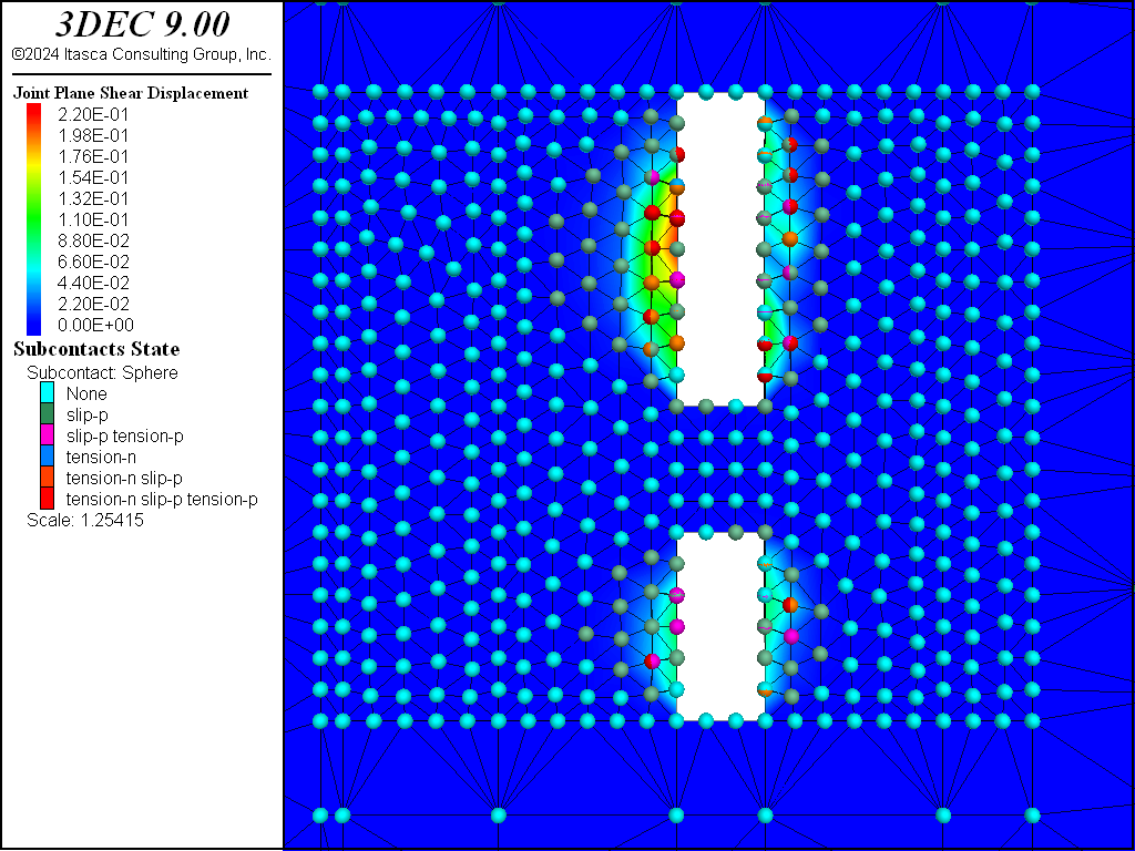
Figure 3: 3DEC plot of shear displacement on Fault #1 following extraction of the upper and lower stopes (view is from the southwest).
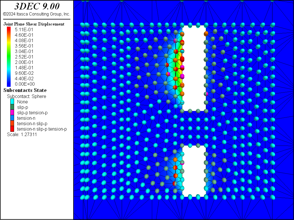
Figure 4: 3DEC plot of shear displacement on Fault #2 following extraction of the upper and lower stopes (view is from the east).
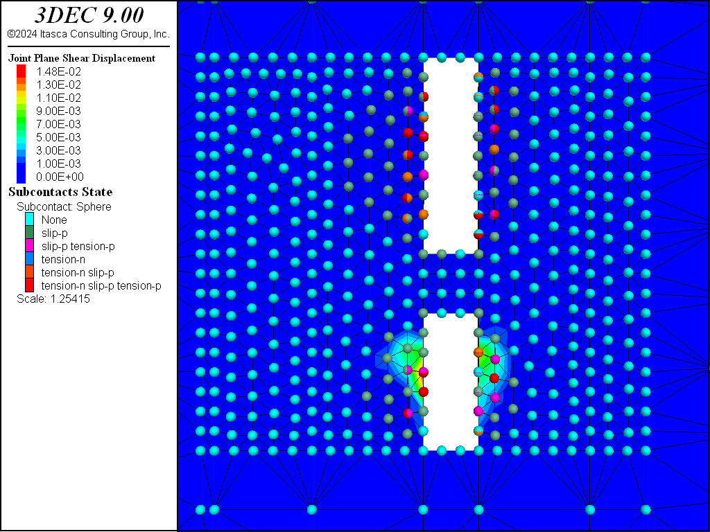
Figure 5: 3DEC plot of shear displacement on Fault #1 following extraction of sill pillar cut #1 (view is from the southwest).
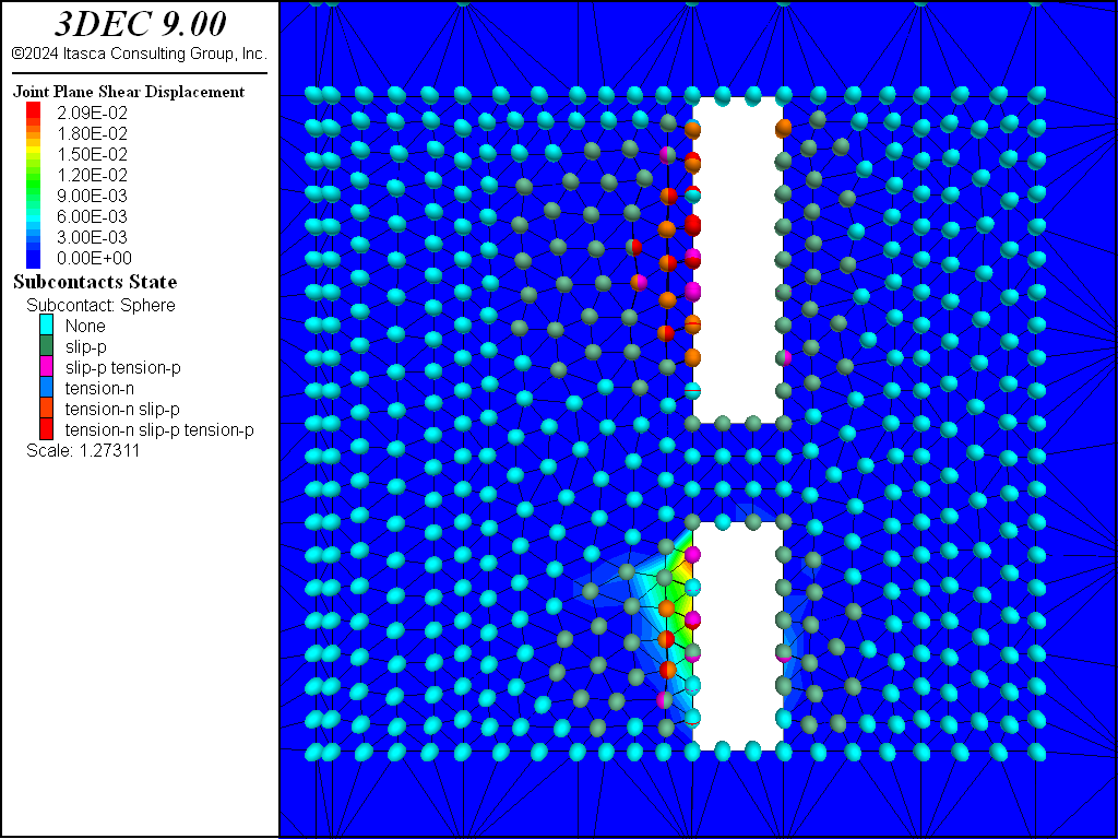
Figure 6: 3DEC plot of shear displacement on Fault #2 following extraction of sill pillar cut #1 (view is from the east).
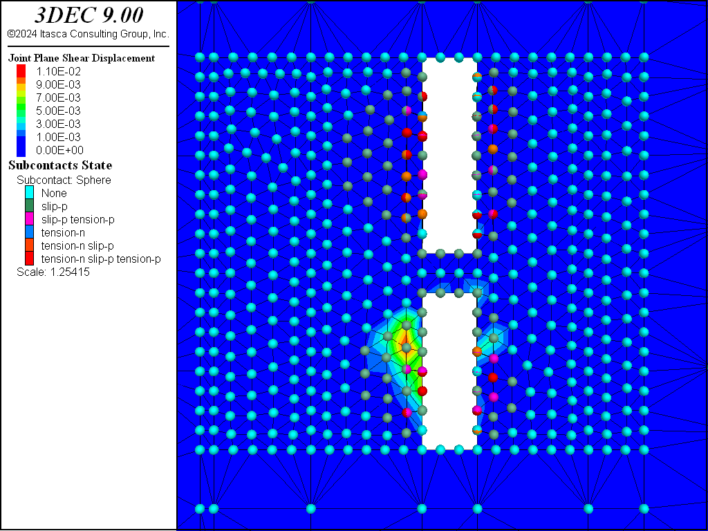
Figure 7: 3DEC plot of shear displacement on Fault #1 following extraction of sill pillar cut #2 (view is from the southwest).
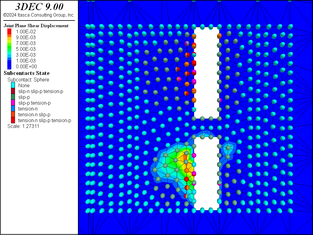
Figure 8: 3DEC plot of shear displacement on Fault #2 following extraction of sill pillar cut #2 (view is from the east).
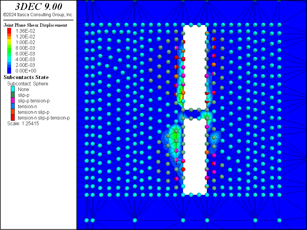
Figure 9: 3DEC plot of shear displacement on Fault #1 following extraction of sill pillar cut #3 (view is from the southwest).
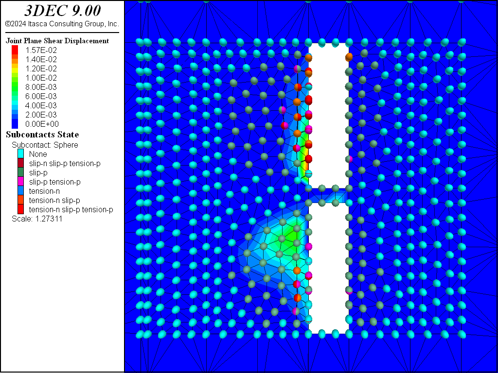
Figure 10: 3DEC plot of shear displacement on Fault #2 following extraction of sill pillar cut #3 (view is from the east).
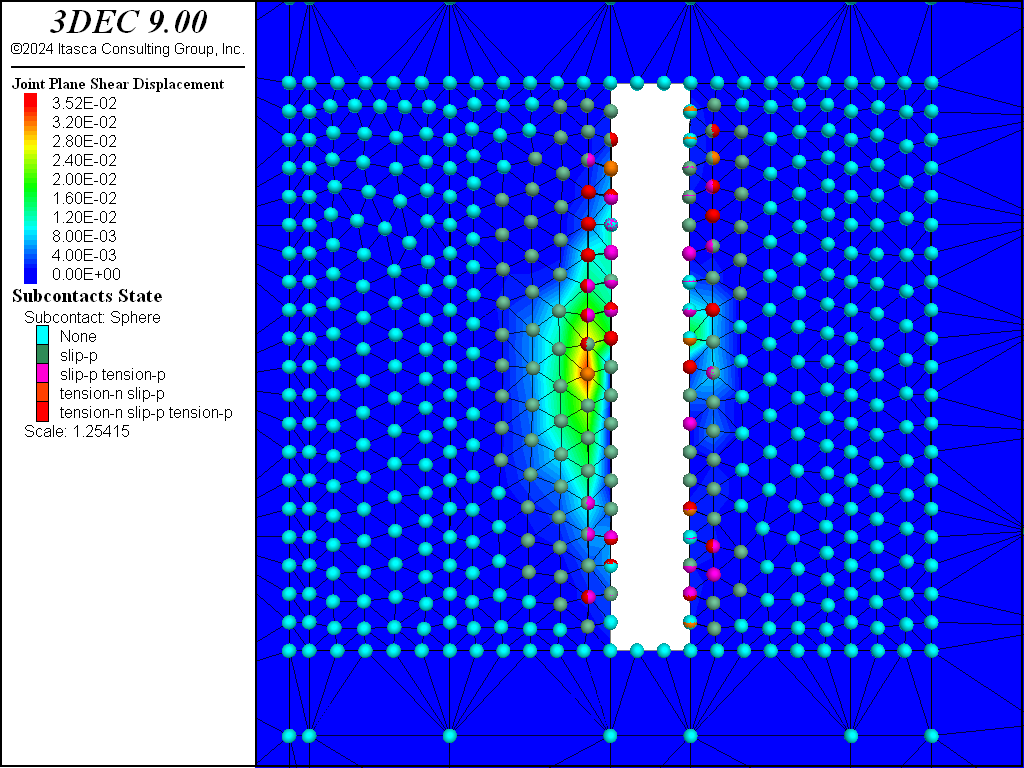
Figure 11: 3DEC plot of shear displacement on Fault #1 following extraction of sill pillar cut #4 (view is from the southwest).
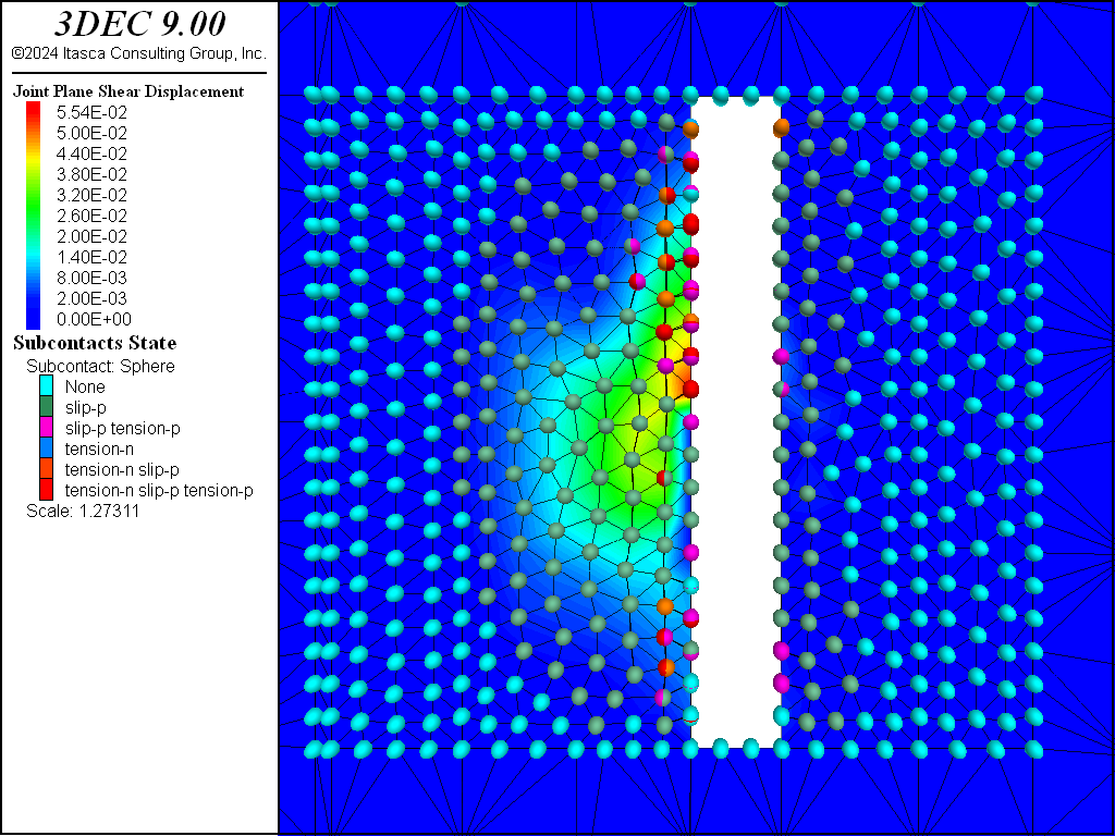
Figure 12: 3DEC plot of shear displacement on Fault #2 following extraction of sill pillar cut #4 (view is from the east).
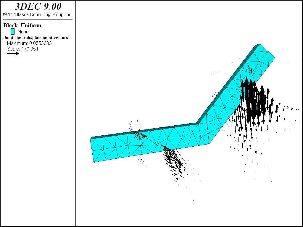
Figure 13: 3DEC vector plot of shear displacement on the faults following extraction of sill pillar cut #4 (plan section at the mid-height of sill pillar cut #4).
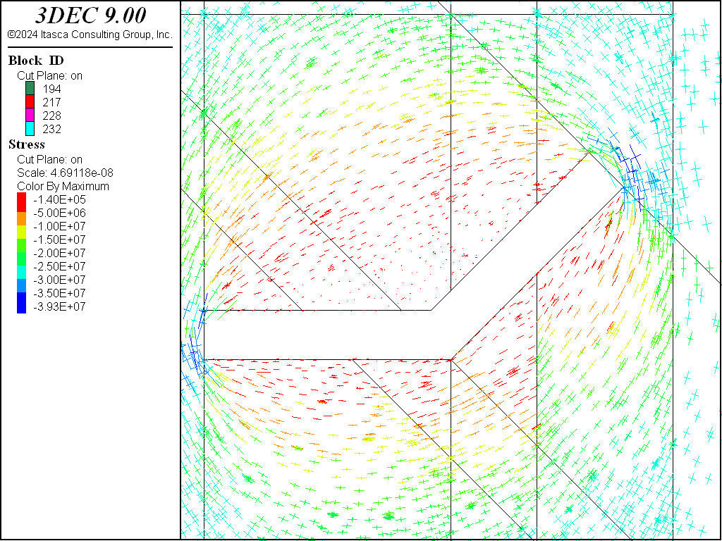
Figure 14: 3DEC vector plot of principal stresses following extraction of sill pillar cut #4 (plan section at the mid-height of sill pillar cut #4).
Data File
seis.dat
model new
model random 10000
model large-strain on

block create brick 880 1105 900 1130 3890 4110
block group 'rock' slot 'geology'

;create orebody
block cut joint-set dip 90 dip-direction 90 origin 950 0 0
block hide range position-x 880 950
block cut joint-set dip 90 dip-direction 90 origin 1000 0 0
block hide range plane position-x 1000 1105
block cut joint-set dip 90 dip-direction 0 origin 0 1000 0
block hide range position-y 900 1000
block cut joint-set dip 90 dip-direction 0 origin 950 1010 0
block hide range position-y 1010 1130
block group 'orebody' slot 'geology'

block hide off
block cut joint-set dip 90 dip-direction 45 origin 1035 1035 0
block hide range plane dip 90 dip-direction 45 origin 1035 1035 0 above
block cut joint-set dip 90 dip-direction 225 origin 1000 1000 0
block hide range plane dip 90 dip-direction 225 origin 1000 1000 0 above
block cut joint-set dip 90 dip-direction 135 origin 1000 1000 0
block hide range plane dip 90 dip-direction 135 origin 1000 1000 0 above
block cut joint-set dip 90 dip-direction 315 origin 1028 1042 0
block hide range plane dip 90 dip-direction 315 origin 1028 1042 0 above
block group 'orebody' slot 'geology'

block hide off range group 'orebody'

;create upper stope
block cut joint-set dip 0 dip-direction 0 origin 0 0 4000
block cut joint-set dip 0 dip-direction 0 origin 0 0 4050
block group 'upper stope' slot 'excavation' range position-z 4000 4050

;create lower stope
block cut joint-set dip 0 dip-direction 0 origin 0 0 3950
block cut joint-set dip 0 dip-direction 0 origin 0 0 3980
block group 'lower stope' slot 'excavation' range position-z 3950 3980

;create sill pillars
block cut joint-set dip 0 dip-direction 0 origin 0 0 3985
block group 'sill pillar 1' slot 'excavation' range position-z 3980 3985
block cut joint-set dip 0 dip-direction 0 origin 0 0 3990
block group 'sill pillar 2' slot 'excavation' range position-z 3985 3990
block cut joint-set dip 0 dip-direction 0 origin 0 0 3995
block group 'sill pillar 3' slot 'excavation' range position-z 3990 3995
block group 'sill pillar 4' slot 'excavation' range position-z 3995 4000
block hide off

;create faults
block cut joint-set dip 90 dip-direction 45 origin 975 1005 0 jointset-id 100
block cut joint-set dip 90 dip-direction 90 origin 1017.5 1017.5 0 ...
  jointset-id 200

;fine zoning around orebody
block cut joint-set dip 90 dip-direction 90 origin 940 0 0
block hide range position-x 880 940
block cut joint-set dip 90 dip-direction 90 origin 1045 0 0
block hide range position-x 1045 1105
block cut joint-set dip 90 dip-direction 0 origin 0 960  0
block hide range position-y 900 960
block cut joint-set dip 90 dip-direction 0 origin 0 1070 0
block hide range position-y 1070 1130
block cut joint-set dip 0 dip-direction 0 origin 0 0 3950
block hide range position-z 3890 3950
block cut joint-set dip 0 dip-direction 0 origin 0 0 4050
block hide range position-z 4050 4110

block zone generate edgelength 5

;intermediate zoning
block hide off
block cut joint-set dip 90 dip-direction 90 origin 910 0 0
block hide range position-x 880 910
block cut joint-set dip 90 dip-direction 90 origin 1075 0 0
block hide range position-x 1075 1105
block cut joint-set dip 90 dip-direction 0 origin 0 930  0
block hide range position-y 900 930
block cut joint-set dip 90 dip-direction 0 origin 0 1100 0
block hide range position-y 1100 1130
block cut joint-set dip 0 dip-direction 0 origin 0 0 3920
block hide range position-z 3890 3920
block cut joint-set dip 0 dip-direction 0 origin 0 0 4080
block hide position-z 4080 4110
block zone generate edgelength 20

;outer zoning
block hide off
block zone generate edgelength 80

model save 'seis-zoned'

================================================================

;join all blocks surrounding faults
block hide off
block hide range plane dip 90 dip-direction 45 origin 975 1005 0 above
block hide range position-x 1017.5 1105
block join on
block hide off
block hide range plane dip 90 dip-direction 45 origin 975 1005 0 below
block hide range position-x 1017.5 1105
block join on
block hide off
block hide range plane dip 90 dip-direction 45 origin 975 1005 0 below
block hide range position-x 880 1017.5
block join on
block hide off
block hide range plane dip 90 dip-direction 45 origin 975 1005 0 above
block hide range position-x 880 1017.5
block join on
block hide off
;
;block properties
block zone cmodel assign mohr-coulomb
block zone property bulk 13.2e9 shear 9.9e9 density 2700 ...
                    cohesion 8e6 friction 43
block zone property bulk 17.6e9 shear 13.2e9 ...
                    density 2700 cohesion 10e6 ...
                    friction 43 range group 'orebody'

;joint properties
block contact property stiffness-normal 1e11 stiffness-shear 1e11 ...
                       friction 30
block contact material-table default property stiffness-normal 1e11  ...
                                              stiffness-shear 1e11 friction 30

;boundary conditions
block gridpoint apply velocity-x 0 velocity-y 0 velocity-z 0 ...
                      range position-x 880
block gridpoint apply velocity-x 0 velocity-y 0 velocity-z 0 ...
                      range position-x 1105
block gridpoint apply velocity-x 0 velocity-y 0 velocity-z 0 ...
                      range position-y 900
block gridpoint apply velocity-x 0 velocity-y 0 velocity-z 0 ...
                      range position-y 1130
block gridpoint apply velocity-x 0 velocity-y 0 velocity-z 0 ...
                      range position-z 3890
block gridpoint apply velocity-x 0 velocity-y 0 velocity-z 0 ...
                      range position-z 4110
;stresses
model gravity 0 0 -9.81
block insitu stress -198.65e6 -264.87e6 -132.44e6 0 0 0 ...
             gradient-z 39.73e3 52.947e3 26.487e3 0 0 0
;
model history mechanical unbalanced-maximum
;initial equilibration
model solve
model save 'seis-ini'

========================================================

;sequential excavating and filling

block excavate range group 'upper stope' or 'lower stope'
model solve
model save 'seis-1'
;
block fill
block contact jmodel assign elastic range group 'upper stope' or 'lower stope'
block contact property stiffness-normal 1e11 stiffness-shear 1e11 ...
              range group 'upper stope' or 'lower stope'
block zone cmodel assign mohr-coulomb range group 'upper stope' or ...
                                                  'lower stope'
block zone property bulk 30e6 shear 14e6 density 2000 cohesion 50e3 ...
                    friction 40 range group 'upper stope' or 'lower stope'

block contact reset displacement
block excavate range group 'sill pillar 1'
model solve
model save 'seis-2'

block fill
block contact jmodel assign elastic range group 'sill pillar 1'
block contact property stiffness-normal 1e11 stiffness-shear 1e11 ...
                       range group 'sill pillar 1'
block zone cmodel assign mohr-coulomb range group 'sill pillar 1'
block zone property bulk 30e6 shear 14e6 density 2000 cohesion 50e3 ...
                    friction 40 range group 'sill pillar 1'

block contact reset displacement
block excavate range group 'sill pillar 2'
model solve
model save 'seis-3'

block fill
block contact jmodel assign elastic range group 'sill pillar 2'
block contact property stiffness-normal 1e11 stiffness-shear 1e11 ...
              range group 'sill pillar 2'
block zone cmodel assign mohr-coulomb range group 'sill pillar 2'
block zone property bulk 30e6 shear 14e6 density 2000 cohesion 50e3 ...
              friction 40 range group 'sill pillar 2'

block contact reset displacement
block excavate range group 'sill pillar 3'
model solve
model save 'seis-4'

block fill
block contact jmodel assign elastic range group 'sill pillar 3'
block contact property stiffness-normal 1e11 stiffness-shear 1e11 ...
              range group 'sill pillar 3'
block zone cmodel assign mohr-coulomb range group 'sill pillar 3'
block zone property bulk 30e6 shear 14e6 density 2000 cohesion 50e3 ...
              friction 40 range group 'sill pillar 3'

block contact reset displacement
block excavate range group 'sill pillar 4'
model solve
model save 'seis-5'
Endnote
| Was this helpful? ... | Itasca Software © 2024, Itasca | Updated: Nov 12, 2025 |
