Loading and Sequential Modeling
By applying different model loading conditions at different stages of an analysis, it is possible to simulate changes in physical loading, such as sequences of excavation and construction. Changes in loading may be specified in a number of ways (e.g., by applying new stress or displacement boundaries, by changing the material model in blocks to either a null material or to a different material model, or by changing material properties).
It is important to recognize that sequential modeling follows the stages of an engineering work. In most analyses, each work stage corresponds to a different static solution following a loading change (i.e., physical time is not a parameter). 3DEC can perform calculations for heat transfer and dynamic mechanical analysis as well (see Dynamic Analysis and Thermal Option). In these cases, a static solution for an equilibrium stress state may be followed, for example, by a dynamic calculation for an applied explosive excitation or a transient calculation for flow through joints.
Time-dependent behavior, on the other hand, cannot be simulated directly. Some engineering judgment must be used to estimate the effects of time. For example, a model parameter may be changed after a predetermined amount of displacement or strain has occurred. This displacement may be estimated to have occurred over a given period of time.
A loading change must cause unbalanced forces to develop in order to effect a change in model response. Therefore, changing the elastic properties will have no effect; changing strength properties will, if the change causes the current stress state to exceed the failure limit.
The recommended approach to sequential modeling is demonstrated by the following example. This problem involves the stability analysis of an underground opening in jointed rock, and includes the evaluation of different types of support measures. The stages to be analyzed are:
equilibration at the in-situ stress state;
excavation of the tunnel; and
application of the tunnel support.
The objective is to investigate the stability of the excavation under in-situ conditions, and assess the effect of the support measures. Two types of support are evaluated: cable bolts and a continuous concrete liner. Note that this model is greatly simplified for rapid execution, but it still illustrates the recommended steps for loading and sequential modeling.
The tunnel is located in rock containing three major faults: one dipping at 65◦ with a dip direction of 40◦; the second dipping at 70◦ with a dip direction of 270◦; and the third dipping at 60◦ with a dip direction of 130◦. The tunnel is horseshoe-shaped and is centered along the y-axis of the model. The tunnel is created with the block cut tunnel command. The model is created with the following series of commands:
tunnel_geom.dat
model new
model random 10000
model large-strain on

; ---- set up tunnel geometry ----

block create brick -10 10  -10 10  -10 10

; --- tunz: FISH function to define tunnel geometry parameters --------
; ... tunnel along Y axis
; ... semi-circular roof, centered at (0,0)
;
fish define tunz

  ; Fill table with x and z coordinates forigin cutting tunnel
  local tab = table.create('tunnel')

; --- coordinates forigin bottom ---
; start from bottom left corner and go around counter-clockwise
  table.x(tab,1) = -4
  table.y(tab,1) = -4
  table.x(tab,2) = 4
  table.y(tab,2) = -4
;
  ; center and radius of circular arc
  local txc =  0.0
  local tzc =  0.0
  local tr  =  4.0

  ; 8 segments
  local seg = 16
  loop i (1,seg)
    local theta = 180.0/(seg-1)*(i-1)*math.degrad
    table.x(tab,i+2) = txc + tr*math.cos(theta)
    table.y(tab,i+2) = tzc + tr*math.sin(theta)
  end_loop

end
;
; ---------------------------------------------------------------------
; (execute function)
[tunz]
;
block group 'rock'
;
; create outer surface
block cut tunnel  radial ...
        table-1 'tunnel' axis 0,-10,0 0,10,0 group 'exc'
;
; --- joints ---  3 joints to form a wedgelength in the roof
;
block cut joint-set dip-direction 270 dip 70 origin 0 0,5.7  jointset-id 10
block cut joint-set dip-direction 40  dip 65 origin 0 0,5.7  jointset-id 10
block cut joint-set dip-direction 130 dip 60 origin 0 0,5.7  jointset-id 10
;
; --- mesh generation ---
block zone generate edgelength 1
;
model save 'tunnel_zoned'
Figure 1 shows the resulting model configuration. The tunnel geometry parameters are defined in the FISH function tunz. The inner region of the tunnel is assigned group exc. Note that the tunnel is created first, and then the physical joint set is generated. Blocks are joined automatically with the block cut tunnel
command. Zone generation is performed separately for the rock blocks, and the interior region of the tunnel to create smaller zones in the region of interest (in and around the tunnel).
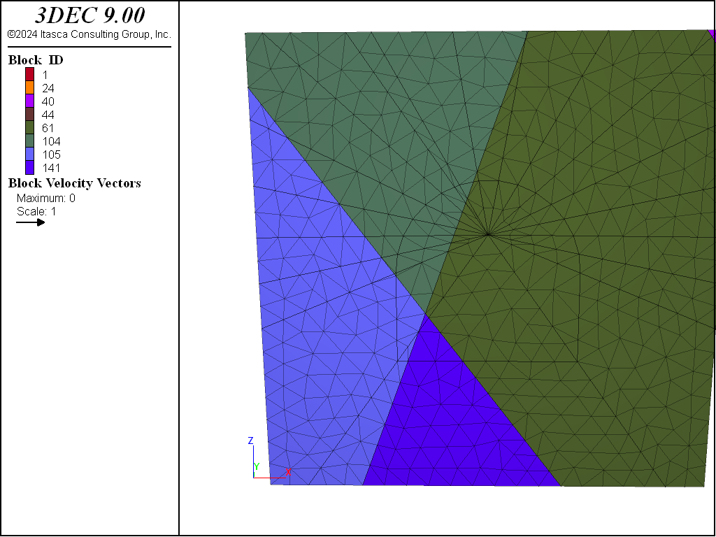
Figure 1: 3DEC model of the tunnel region.
Next, constitutitve models and material properties are assigned to the zones and the joints. Note that stress/stiffness units of MPa are used, therefore density in kg/m^3 must be divided by 1e6.
The in-situ stress state and boundary conditions are applied, assuming the tunnel is at a depth of 200 m and the ratio of horizontal to vertical stress is 0.5. Note that for a practical simulation, the boundaries are too close to the tunnel excavation and should be moved to a greater distance to minimize their influence on the model results.
Finally, gravity is turned on and the model is solved to initial equilibrium. The commands to assign material properties and achieve the initial stress state are shown below.
tunnel_ini.dat
; ---- Bring to initial stress state ---
;
model restore 'tunnel_zoned'
;
; --- properties - stress units are MPa ---
;
; --- rock ---
; density = 2700 kg/m3 -> 0.0027
; E=50 GPa, Poisson's ratio=0.2
block zone cmodel assign elastic
block zone property density 0.0027 young 50000 poisson 0.2
;
; --- joints ---
block contact jmodel assign mohr
block contact property stiffness-normal 10000 stiffness-shear 2000 friction 25
block contact material-table default property stiffness-normal 10000 ...
  stiffness-shear 2000 friction 25

; gravity
model gravity 0 0 -10
;
; --- insitu stress state ---
; assume center of tunnel at 200 m depth, top of model is at is at 190 m
block insitu topography ratio-x 0.5 ratio-y 0.5 overburden [-190*0.0027*9.81]
;
; --- boundary conditions forigin insitu stress state ---
block face apply stress 0 0 [-190*0.0027*10]  0 0 0 range position-z 10.0
; bottom
block gridpoint apply velocity-z 0 range position-z -10.0
; sides
block gridpoint apply velocity-x 0 range position-x -10.0
block gridpoint apply velocity-x 0 range position-x  10.0
block gridpoint apply velocity-y 0 range position-y -10.0
block gridpoint apply velocity-y 0 range position-y  10.0
;
; --- histories to monitorigin convergence ---
history interval=1
model history mechanical unbalanced-maximum
; top of model
block history name 'X-Disp' displacement-x position 0 0 10
block history name 'Y-Disp' displacement-y position 0 0 10
block history name 'Z-Disp' displacement-z position 0 0 10
;
model solve convergence 1
model save 'tunnel_ini'
The maximum unbalanced force in the model and displacements at the top boundary are monitored to help make sure that an initial equilibrium stress state is reached. Figure 2 shows the x-, y- and z-displacement histories for the gridpoint (x = 0, y = 0, z = 10) at the top of the model.
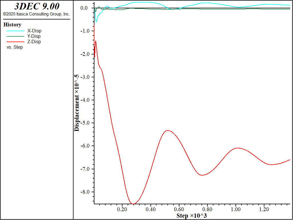
Figure 2: Displacement histories at the top of the model during initial stress installation.
If the tunnel is excavated without support, a rock wedge detaches and falls from the roof. This is shown by running tunnel_exc.dat.
The tunnel is excavated gradually with the block relax command. This excavates the tunnel and applies reaction forces to prevent inward movement. The applied forces are then gradually reduced to 0 over the number of steps specified. This is done to prevent a shock to the system that would occur if the tunnel blocks were excavated instantaneously.
The z-displacement at a location in the roof is monitored while the model is cycled. Figure 3 plots the z-displacement history and indicates that the position is moving downward. Figure 4 shows a close-up view of the detached wedge, with surrounding blocks hidden for better viewing.
tunnel_exc.dat
model restore 'tunnel_ini'

; excavate interiorigin blocks by gradually reducing forces on the surface
; over 1000 steps
block relax nonlinear 1000 range group 'exc'
;
; history point at tunnel roof
block gridpoint initialize displacement 0 0 0
model mechanical time-total 0
history delete

; history of point in wedge
block history name 'Vertical Displacement' displacement-z position 0 -0.2 4.3

;
model cycle 5000
;
model save 'tunnel_exc'

block hide range plane dip 60 dip-direction 130 origin 0 0 5.7 above
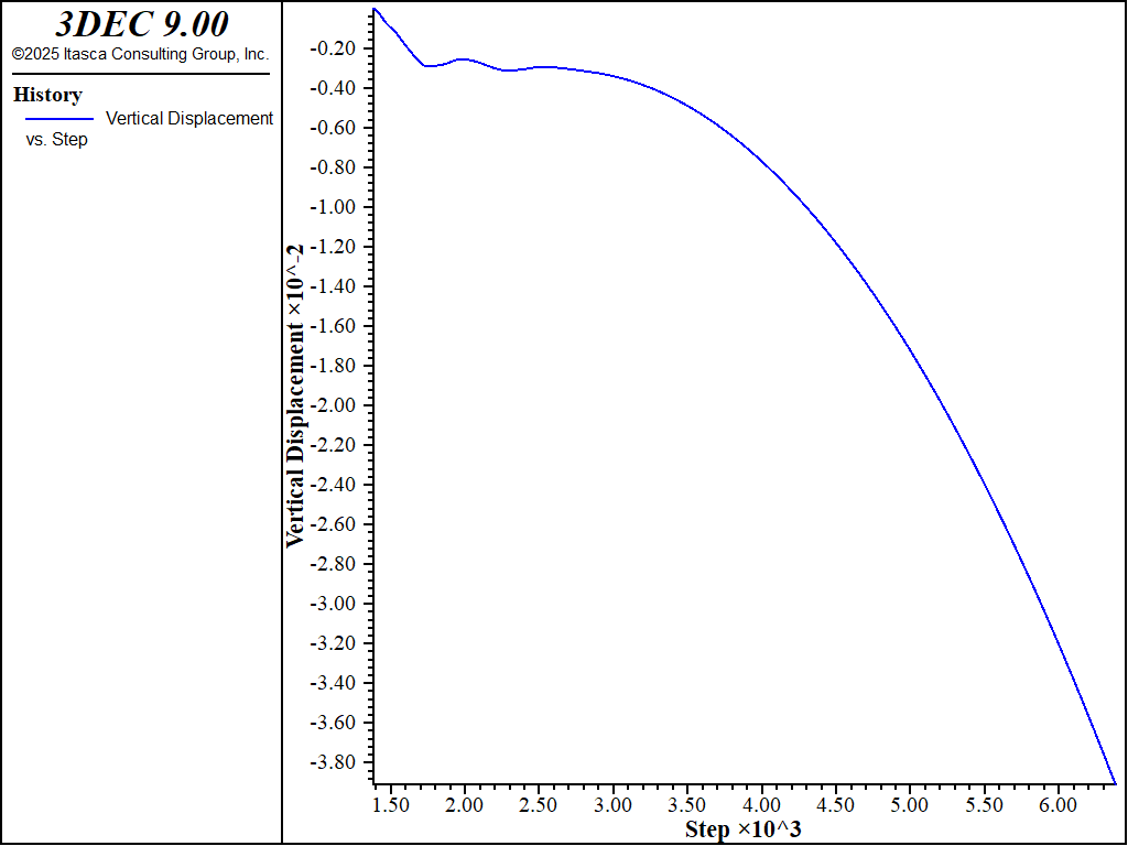
Figure 3: Vertical Displacement history in the tunnel roof.
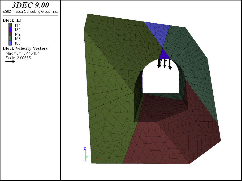
Figure 4: Close-up view of wedge in roof (surrounding blocks hidden).
Next, the effect of rock bolt support is evaluated. Fully bonded cable elements are installed using the structure cable create command. See Cable Structural Elements for a detailed description of this type of structural support.
tunnel_cables.dat lists the commands to excavate the tunnel and install the cable elements. Note that we use the block excavate command rather than the block delete command so we can view the excavated region. Figure 5 shows the location of the cable elements around the excavation.
tunnel_cables.dat
model restore 'tunnel_ini'
;
; delete interiorigin blocks
block excavate range group 'exc'
;
;
; --- install cable elements ---
structure cable create  by-line -8 -5 -2   -4.05 -5 -2  segments 4
structure cable create  by-line -8  0 -2   -4.05  0 -2  segments 4
structure cable create  by-line -8  5 -2   -4.05  5 -2  segments 4
structure cable create  by-line -6.8 -5  6.8   -2.85 -5  2.85  segments 4
structure cable create  by-line -6.8  0  6.8   -2.85  0  2.85  segments 4
structure cable create  by-line -6.8  5  6.8   -2.85  5  2.85  segments 4
;
structure cable create  by-line 8 -5 -2   4.05 -5 -2  segments 4
structure cable create  by-line 8  0 -2   4.05  0 -2  segments 4
structure cable create  by-line 8  5 -2   4.05  5 -2  segments 4
structure cable create  by-line 6.8 -5  6.8   2.85 -5  2.85  segments 4
structure cable create  by-line 6.8  0  6.8   2.85  0  2.85  segments 4
structure cable create  by-line 6.8  5  6.8   2.85  5  2.85  segments 4
;
structure cable create by-line 0 -5 4.1   0 -5 8  segments 4
structure cable create by-line 0  0 4.1   0  0 8  segments 4
structure cable create by-line 0  5 4.1   0  5 8  segments 4
;
; start with high grout strength
structure cable property cross-sectional-area 5e-4 young 100000 ...
  yield-tension 0.55 grout-stiffness 250 grout-cohesion 1000
;
history delete
block gridpoint initialize displacement 0 0 0

; history of point in wedge
block history name 'Vertical Displacement' displacement-z position 0 -0.2 4.3
;
; use combined damping for cables (soon to be default?)
structure mechanical damping combined-local
model solve convergence 1
;
; set real grout strength
structure cable property grout-cohesion 0.8
;
model solve convergence 1
;
model save 'tunnel_cables'
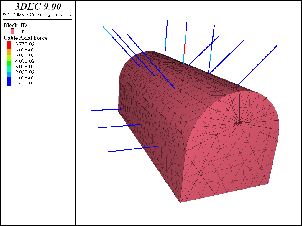
Figure 5: Cable bolts positioned around the tunnel excavation contoured by axial force.
The roof is stabilized when the cables are added. The z-displacement history now indicates that the wedge movement stops at roughly 4 mm displacement (see Figure 6). The axial forces that develop in the support are greatest in the roof elements as shown in Figure 5.
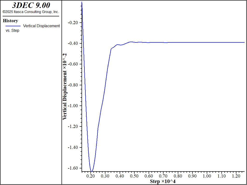
Figure 6: Vertical Displacement history in the tunnel roof with cable support.
The model of a tunnel excavation and support sequence should simulate the change in stresses around the tunnel as the excavation advances, before the tunnel support is installed. This can be done in a 3DEC model by excavating the tunnel in sections and installing support after each excavation section. This is the recommended approach to simulate support loading changes due to tunnel advancement.
Alternatively, in this simplified model we simulate the effect of tunnel advancement by reducing the tractions at the tunnel periphery gradually, and installing the liner before the tractions are completely removed. This demonstrates an approach for simulating a gradual excavation of a tunnel section. The data file below shows this approach.
tunnel_liner.dat
model restore 'tunnel_ini'

; excavate tunnel blocks and reduce stress reduction over 1000 steps
block relax linear 1000 minimum 0.5 face-group 'surface' range group 'exc'

; history of point in wedge
block history name 'Vertical Displacement' displacement-z position 0 -0.2 4.3

model cycle 1000

; solve at 50% relaxation
model solve convergence 1

; remove loads
block relax delete

; add liner to arch
; tolerance is required since blocks will have shifted a bit during initial excavation
structure liner create by-block-face tolerance 1e-3 ...
  range group 'surface' position-z -3.9 4
structure liner cmodel assign elastic

; properties in MPa
structure liner property coupling-friction-shear 60 ...
  coupling-cohesion-shear .5e6 coupling-stiffness-normal 1e3 ...
  coupling-stiffness-shear 1e3
structure liner property young 15e3 poisson .15 thickness .20 ...
  coupling-yield-normal .3e6

; use combined damping forigin liners (soon to be default?)
structure mechanical damping combined-local
model solve convergence 1
;
model save 'tunnel_liner'
The block relax command is used with the minimum keyword to apply 50% of the in-situ stress state to the liner-rock interface, to the tunnel surface. The tractions applied to the tunnel surface are reduced by 50% over 1000 steps and then then model is cycled to an equilibrium state with the tunnel tractions held constant. Note that the face-group keyword is used to assign a group name to the faces on the surface of the excavation. This is used later when liner elements are installed on these faces.
Next, the tractions are removed completely and the liner is installed (with the structure liner create command). Figure 7 shows the liner elements created for this model. The model is cycled to a new equilibrium state. The load that develops in the liner is due to the reduction of the tractions from 50% to zero.
This plot is generated by choosing in the Liner plot item, then setting the Surface X-coordinate to be 0,1,0 (down to tunnel) and plotting the moment M_y. The plot shows large moments around the falling wedge as expected.
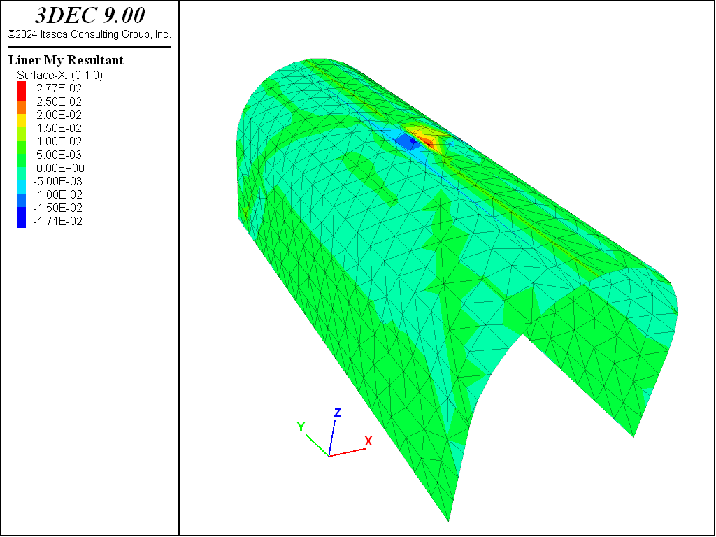
Figure 7: Liner elements around the tunnel contoured by maximum moment.
Note that the selection of a 50% reduction in tunnel tractions in this example is arbitrary and only for demonstration purposes.
The displacement of the roof is shown in Figure 8. Roughly 1.5 mm of vertical displacement occurs when the tractions are reduced by 50%, and an additional 1.7 mm displacement after the tunnel tractions are completely removed and the liner is installed.
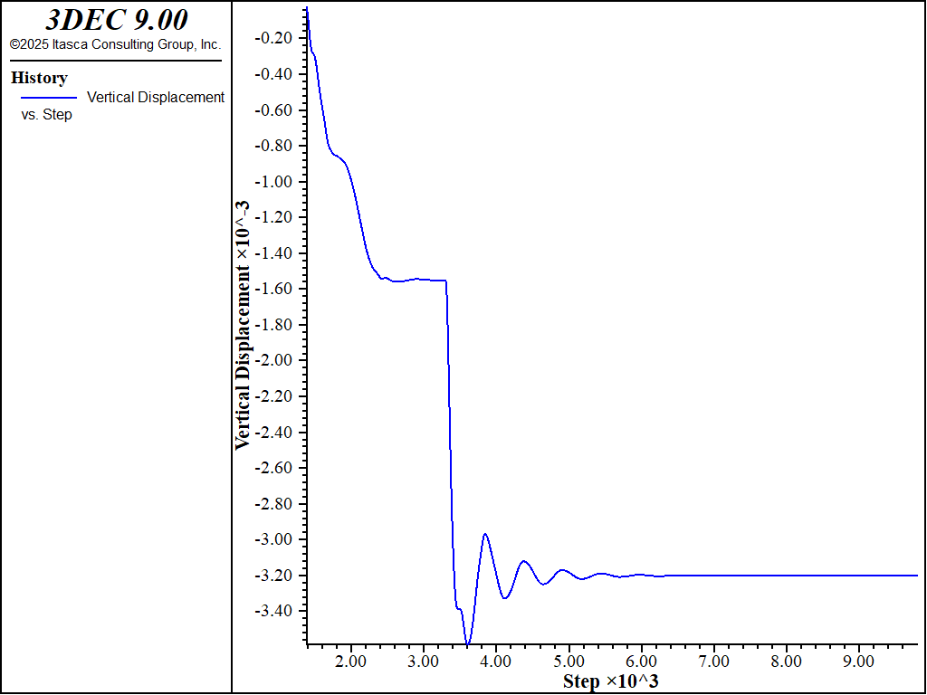
Figure 8: Vertical Displacement history in the tunnel roof with liner support.
| Was this helpful? ... | Itasca Software © 2024, Itasca | Updated: Nov 12, 2025 |
