Creating Single Blocks
The 3DEC model geometry must represent the physical problem to an extent sufficient to capture the dominant mechanisms related to the geologic structure in the region of interest. The following aspects must be considered:
How much detail should be used to represent the geologic structure (e.g., faults, joints, bedding planes, etc.)?
How will the location of the model boundaries influence model results?
If deformable blocks are used, what density of zoning is required for accurate solution in the region of interest?
All three aspects determine the size of the 3DEC model that is practical for analysis.
As mentioned above, there are two different starting points in building 3DEC models. The first method is to describe a simple starting shape and slice it up to create the desired geometrical features. The second involves defining complex polyhedral shapes and putting them together to form the continuous mass. Both of these approaches make use of the block create command.
There are six forms of the block create command available in 3DEC:
BLOCK CREATE polyhedron
BLOCK CREATE brick
BLOCK CREATE drum
BLOCK CREATE prism
BLOCK CREATE tunnel
BLOCK CREATE tetrahedron
By using the block create polyhedron command, polyhedra of virtually any shape can be defined. Each face is defined by a list of vertex coordinates. The list must be entered in clockwise order, looking at the face from outside the polyhedra. All points on a face must be coplanar, and the resulting polyhedra created by the face commands must be convex. Continuation lines are allowed, but the coordinates for each vertex may not be split between lines. All faces required to close the polyhedra must be specified. A simple example of using the BLOCK CREATE POLYHEDRON command to generate a cube (1 unit on each side) is:
A cube generated with the BLOCK CREATE POLYHEDRON command
model new
block create polyhedron &
face 0,0,0 1,0,0 1,1,0 0,1,0 &
face 0,0,0 0,0,1 1,0,1 1,0,0 &
face 0,0,0 0,1,0 0,1,1 0,0,1 &
face 1,1,1 1,1,0 1,0,0 1,0,1 &
face 1,1,1 1,0,1 0,0,1 0,1,1 &
face 1,1,1 0,1,1 0,1,0 1,1,0
The model created with the example is shown in Figure 1. In this case, a simple regular rightangled solid is produced. The command can also be used to create complex shapes. Because of the large amount of input required, the BLOCK CREATE POLYHEDRON command is often best used in conjunction with the external preprocessor programs (e.g. Griddle).
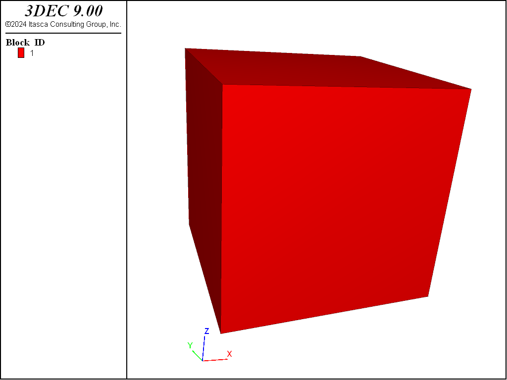
Figure 1: Cubic model created with the BLOCK CREATE POLYHEDRON command
The block create brick command provides a simpler alternative when the problem region is a regular six-sided “brick-shaped” region. The parameters for the brick keyword are the x-, y-, and z-limits of the solid (i.e., the region extends from coordinates xl to xu in the x-direction, from coordinates yl to yu in the y-direction, and from coordinates zl to zu in the z-direction). For example, to create the same model generated in Figure 1, the command is:
A cube generated with the BLOCK CREATE BRICK command
model new
block create brick 0,1 0,1 0,1
Note that if all dimensions are the same, it is only necessary to give the x limits. Therefore the above command could be abbreviated to block create brick 0,1.
block create drum creates drum-shaped blocks with parallel ends. This is similar to block create prism but uses a simpler command syntax.
The block create prism command is an extension of the BLOCK CREATE BRICK command to create prism-shaped polyhedra. The two parallel faces of the prism are defined by an arbitrary number of vertices. The opposing vertices on each face are then automatically connected to form the prism. The first face (face-1) is defined by vertices entered in either a clockwise or counterclockwise order. The opposite face (face-2) must have its vertices entered in the same order as the corresponding vertices for face-1. Faces 1 and 2 must be planar and convex. The prism shown in Figure 2 is created by the commands listed below:
model new
block create prism &
  face-1 (0.0,0.0,0.0 ) (-0.5,0.0,0.87) (-0.5,0.0,1.87) (0.0,0.0,2.74) &
    (1.0,0.0,2.74) ( 1.5,0.0,1.87) ( 1.5,0.0,0.87) (1.0,0.0, 0.0) &
  face-2 (0.0,4.0,0.0 ) (-0.5,4.0,0.87) (-0.5,4.0,1.87) (0.0,4.0,2.74) &
    (1.0,4.0,2.74) ( 1.5,4.0,1.87) ( 1.5,4.0,0.87) (1.0,4.0, 0.0)
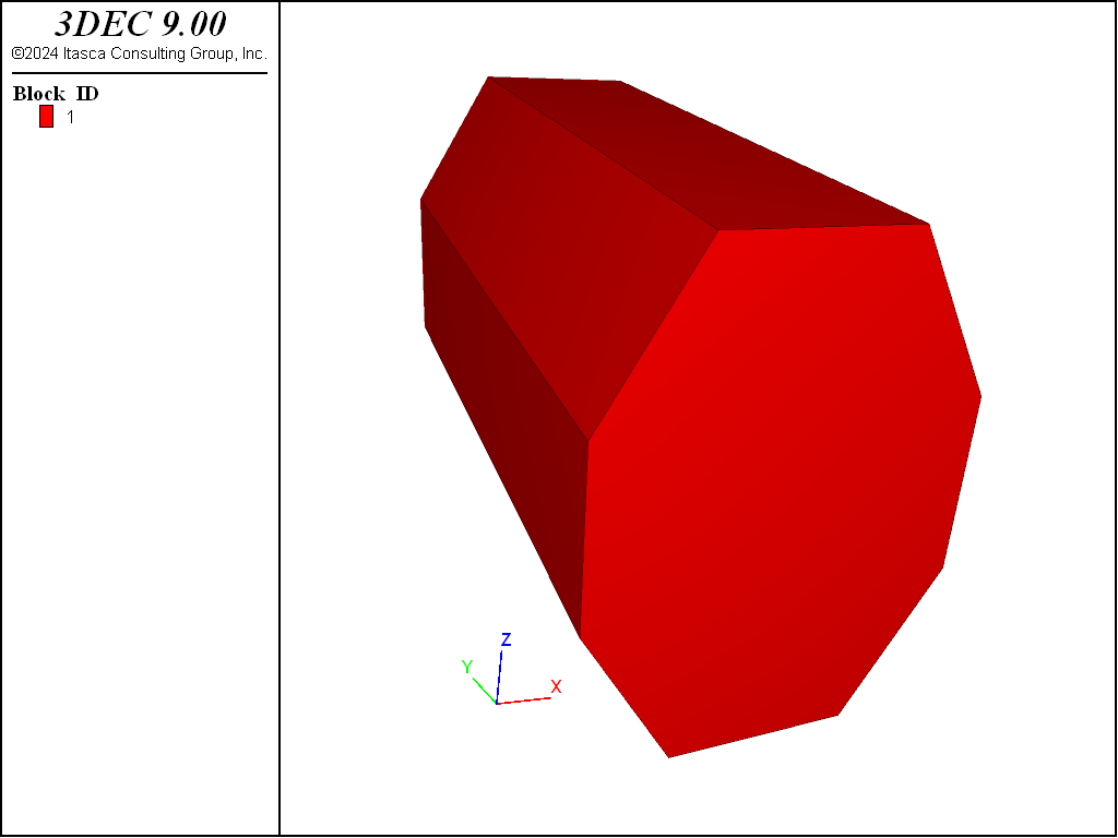
Figure 2: An octahedral-shaped prism generated with the BLOCK CREATE PRISM command
The block create tunnel command is specifically designed to generate a circular-shaped tunnel model. This command works by constructing the model with individual blocks. This is in contrast to the block cut tunnel command, which cuts an arbitrarily shaped tunnel out of an existing block. The user needs only to specify the orientation, dimensions and number of blocks to be used for the tunnel. Additional jointing can be added with the block cut command, if desired. For example, to create a tunnel model with the following dimensions:
radius |
2.0 m |
length |
20.0 m |
outside boundary |
3.0 r |
dip |
horizontal |
heading |
south |
blocks in each octant |
1 |
annular blocks |
2 |
blocks along the axis |
3 |
Use the BLOCK CREATE TUNNEL command as given below.
A tunnel model generated with the BLOCK CREATE TUNNEL command
model new

block create tunnel radius=2 length=-10,10 radius-ratio=3.0 ...
 dip=0 dip-direction=0 ...
 blocks-radial=2 blocks-tangential=1 blocks-axial=3

block delete range position-x -2,2 position-y -10,10 position-z -2,2
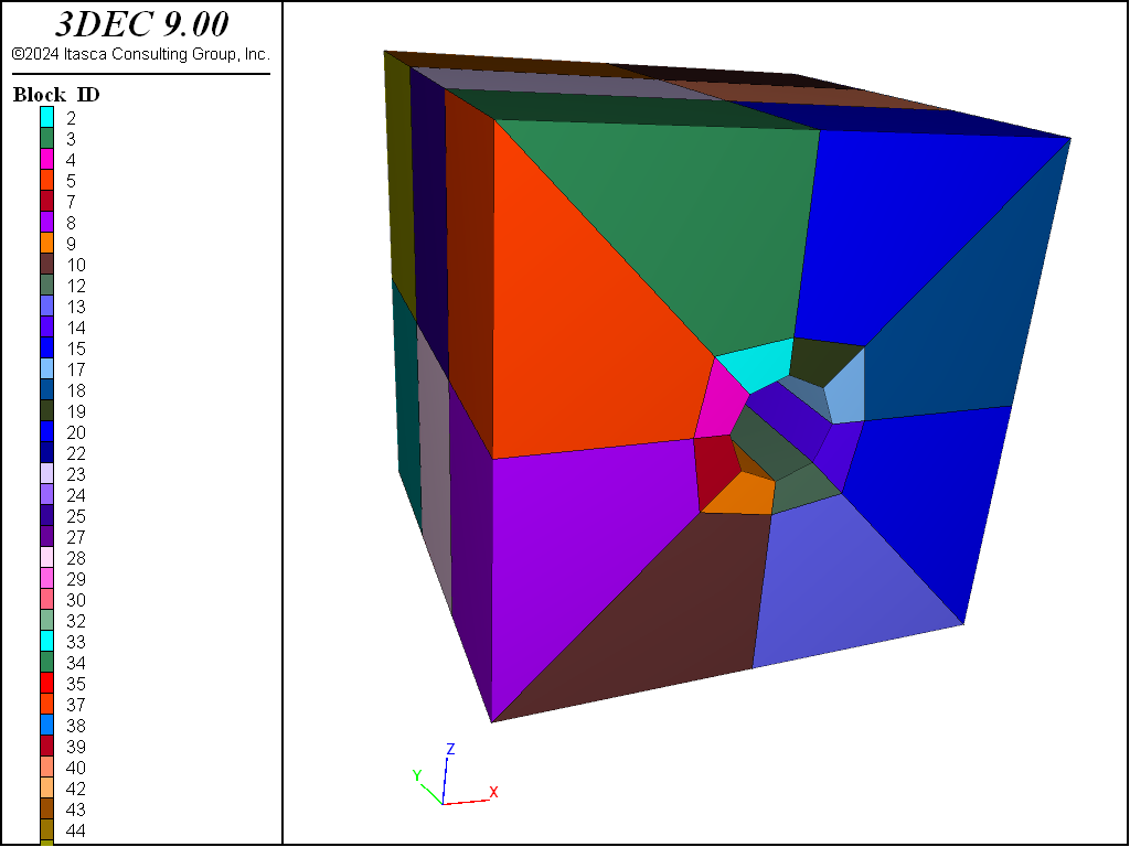
Figure 3: Tunnel model created with the POLYHEDRON tunnel command
The block create tet command creates a tetrahedral block by specifying the four vertex coordinates. Vertices can be listed in any order This command is generally used when importing or exporting from other programs (or from 3DEC itself).
| Was this helpful? ... | Itasca Software © 2024, Itasca | Updated: Nov 12, 2025 |
