Topographical Stresses
The command block insitu topograph automatically calculates gravity loading in models that have an
irregular top surface. The stresses are calculated based on the density of the overlying materials
and specify \(K_o\) values.
Note that the stresses are not exactly correct since they do not account for the horizontal variations related to the topography. It is recommended that a model by cycled to equilibrium after using the block insitu topograph command.
The example below shows a model with an irregular topography and also a zone of less dense material. The calculated stresses in the joints and the zones reflect the topography and the zone densities.
model new
geometry import 'topo.dxf'
geometry import 'blob.dxf'
;
block create brick 500 6500 -500 5500 -1000 3000
;
block densify segments 6 6 4
;
block densify repeat 4 range geometry-distance 'topo' set 'blob' gap 0 extent
;
block group 'rock'
block group 'topo' range geometry-space 'topo' count odd direction 0 0 -1
block delete range group 'topo'
;
block group 'light' range geometry-space 'blob' count odd
;
block tolerance 0.01
;
block cut joint-set origin 2500 2500 2500 dip 60 dip-direction 90 spacing 500
;
block zone generate edgelength 100
;
block zone cmodel elastic
block zone property density 2500 bulk 1e7 shear 0.6e7 range group 'rock'
block zone property density 1500 bulk 1e7 shear 0.6e7 range group 'light'
block contact property stiffness-normal 1e8 stiffness-shear 1e8
;
model gravity 0 0 -9.81
;
block insitu topography ratio-x 0.5 ratio-y 0.5

model save 'topo'
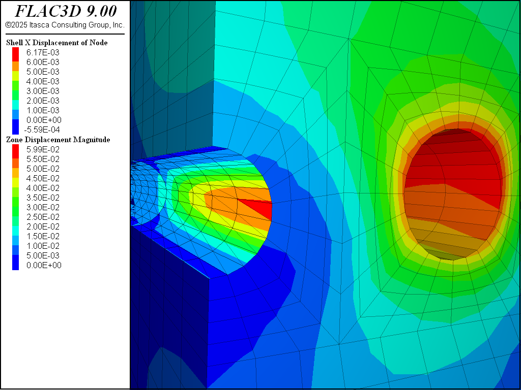
Figure 1: Stresses in model due to topography.
| Was this helpful? ... | Itasca Software © 2024, Itasca | Updated: Nov 12, 2025 |
