Transferring Field Stresses to Model Stresses
Stresses are usually obtained in one of three ways:
Gravitational loading is assumed along with ratios for the horizontal stress based on previous experience at the site or at nearby sites;
Stress maps are used to determine the horizontal stresses (e.g. http://www.world-stress-map.org/);
In-situ stress measurements are obtained.
For the first two methods, stresses can generally be assigned with one or more block insitu topography commands. When one or more actual measurements have been obtained, the problem is more challenging. Usually the measurements are a reflection of the stress at a single point and the stress is likely to vary throughout the model volume. In this case, the block insitu principal may be useful. This command allows you to specify the principal stresses at a location (keyword origin) and then supply a gradient in the \(z\)-direction. Unlike the block insitu stress command, only one gradient value is supplied (the change in stress per unit of length in the \(z\) direction). Changes in all of the stress components are then calculated automatically to ensure that there is no rotation of the principal stress directions throughout the model. An example is shown below.
model new
model random 10000

block create brick 0,100  0,100  -650,-550
;
block zone generate edgelength 10

block zone cmodel assign elastic
block zone property  density 2500 bulk 8e9 shear 5e9

model gravity 0 0 -10

; note that 'minimum' refers to the maximum compressive stress
block insitu principal minimum -60e6 dip-minimum 11 ...
  dip-direction-minimum 270 maximum -15e6 dip-maximum 79 ...
  dip-direction-maximum 90 intermediate -44e6 ...
  origin 50 50 -600 ...
  gradient-z [2500*10]
;
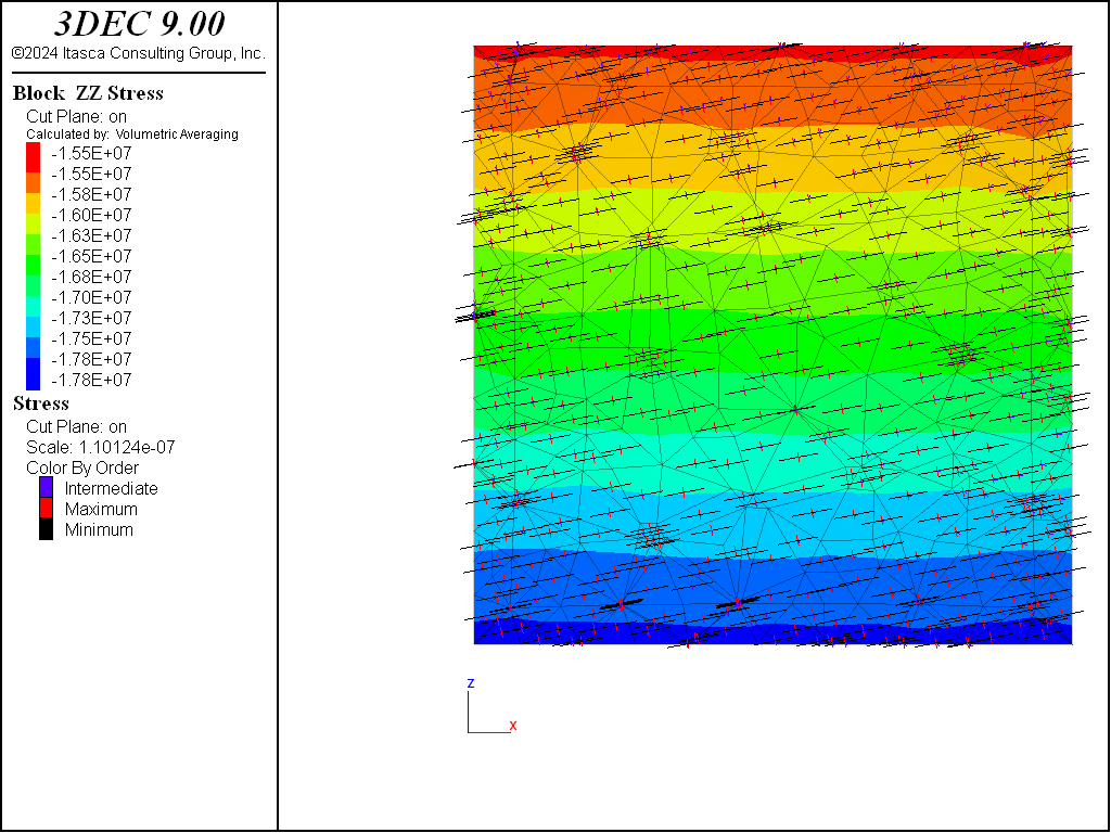
Figure 1: Cross-section a model with principal stresses assigned showing zz-stress contours and stress tensors.
It is also possible to assigned stress boundary conditions to match the initial stresses using the block face apply stress-principal. It is not recommended to do this for all boundaries because the principal stresses will liekly not line up with the boundary directions and this will cause the whole model to rotate. At least one boundary should be fixed.
Commonly, all boundaries are fixed when executing these types of models. Assuming that the boundaries to not align with the principal stress directions, this will cause shear stresses to build up close to the boundaries. The user should be careful to ensure that the fixed boundaries are far enough away from the region of interest that these spurious shear stresses do not affect the results.
| Was this helpful? ... | Itasca Software © 2024, Itasca | Updated: Nov 12, 2025 |
