Damping
General Comments
As described in the first section of 3DEC Theory and Background, 3DEC uses a dynamic algorithm for problem solution. Natural dynamic systems contain some degree of damping of the vibrational energy within the system; otherwise, the system would oscillate indefinitely when subjected to driving forces. Damping is due, in part, to energy loss as a result of slippage along contacts of blocks within the system, internal friction loss in the intact material, and any resistance caused by air or fluids surrounding the structure. 3DEC is used to solve two general classes of mechanical problems: quasi-static and dynamic. Damping is used in the solution of both classes of problems, but quasi-static problems require more damping. Two types of damping (mass-proportional and stiffness-proportional) are available in 3DEC. Mass-proportional damping applies a force which is proportional to absolute velocity and mass, but in the direction opposite to the velocity. Stiffness-proportional damping applies a force, which is proportional to the incremental stiffness matrix multiplied by relative velocities or strain rates, to contacts or stresses in zones. In 3DEC, either form of damping may be used separately or in combination. The use of both forms of damping in combination is termed Rayleigh damping (Bathe and Wilson 1976). For solution of quasi-static problems using finite difference schemes, mass-proportional damping is generally used (Otter et al. 1966). 3DEC allows use of an automatic “adaptive” viscous damping scheme developed by Cundall (1982) for solution of quasi-static problems. These schemes are discussed in 3DEC Theory and Background. For dynamic analyses, either mass-proportional or stiffness-proportional, or both (i.e., Rayleigh), forms of damping may be used, as described in the next section.
Rayleigh Damping
In performing dynamic analysis with any code, it is usually necessary to account for energy losses in the physical system (e.g., heat, hysteresis) which are not accounted for in the numerical algorithm. In general, very little damping is used for highly elastic systems, and more damping is used for geomechanical materials, especially soils.
In the continuum analysis of structures, proportional Rayleigh damping is typically used to damp the natural oscillation modes of the system. In dynamic finite-element analysis, a damping matrix, \(C\), is formed with components proportional to the mass (\(M\)) and stiffness (\(K\)) matrices,
where:
\(\alpha\) = the mass-proportional damping constant; and
\(\beta\) = the stiffness-proportional damping constant.
For a multiple degrees-of-freedom system, the critical damping ratio, \(\xi_i\), at any angular frequency of the system, \(\omega_i\), can be found from (Bathe and Wilson 1976)
or
The critical damping ratio, \(\xi_i\), is also known as the fraction of critical damping for mode \(i\) with angular frequency, \(\omega_i\).
Figure 1 shows the variation of the normalized critical damping ratio with angular frequency, \(\omega_i\). Three curves are given: mass or stiffness components only, and the sum of both components. As shown, mass-proportional damping is dominant at lower angular frequency ranges, while stiffness-proportional damping dominates at higher angular frequencies. The curve representing the sum of both components reaches a minimum at
or
The fundamental frequency is then defined as
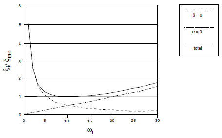
Figure 1: Variation of normalized critical damping ratio with angular frequency.
The required input parameters to specify Rayleigh damping in 3DEC are \(f_{\min}\) (input parameter freq) and \(\xi_{\min}\) (input parameter fcrit).
For the case shown in Figure 1, \(\omega_{\min}\) = 10 radians per second, and \(\xi_{\min}\) = 1. Note that the damping ratio is almost constant over at least a 3:1 frequency range (e.g., from 5 to 15). Since damping in geologic media is known to be predominately hysteretic (Gemant and Jackson 1937; Wegel and Walther 1935), and hence independent of frequency, \(\omega_{\min}\) is usually chosen to lie in the center of the range of frequencies present in the numerical simulation. In this way, hysteretic damping is simulated approximately.
From the preceding equations and Figure 1, it can be seen that at frequency \(\omega_{\min}\) (or \(f_{\min}\)), and only at that frequency, mass damping and stiffness damping each supply half of the total damping.
Example of Different Damping Techniques
In order to demonstrate how Rayleigh damping works in 3DEC, the results of the following four damping cases involving a block sitting on a fixed block with gravity suddenly applied can be compared:
undamped;
Rayleigh damping (both mass and stiffness damping);
mass damping only; and
stiffness damping only.
The data file for each of these cases follows.
Data File
; -------------------------------------------
;  Block under gravity - 3 critically damped cases
; -------------------------------------------
model new
model configure dynamic
model large-strain on

block create brick 0 10 0 1 0 10
block cut joint-set origin 0 0 5

block fix range position-z 0 5
model gravity 0 0 -10

block property density 1000

block contact generate-subcontacts
block contact jmodel assign mohr
block contact property stiffness-normal 5e7 stiffness-shear 5e7
block contact material-table default property stiffness-normal 5e7 ...
                                              stiffness-shear 5e7

block mechanical damping rayleigh 0 0

history interval 1
block history velocity-z position 0 0 10
block history displacement-z position 0 0 10
model history dynamic time-total

model save "damp"

;no damping
model cycle 100
model title "Vertical displacement v time (undamped)
model save "damp-undamped"

;mass and stiffness
model restore "damp"
history interval 10
block mechanical damping rayleigh 1 16
model cycle 500

model title "Vertical disp v time (MASS & STIFFNESS DAMPED; damp 1 16)"
model save "damp-mass-stiff"

;mass only
model restore "damp"
block mechanical damping rayleigh 2 16 mass
model cycle 100
model title "Vertical disp v time (MASS DAMPED; damp 2 16 mass)"
model save "damp-mass"

;stiffness only
model restore "damp"
block mechanical damping rayleigh 2 16 stiffness
model cycle 1000
model title "Vertical disp v time (STIFFNESS DAMPED; damp 2 16 stiff)"
model save "damp-stiff"
;
program return
In the first case, with no damping, a natural frequency of oscillation of approximately 16 cycles/sec can be observed (see Figure Figure #dyn-damp-ptte). The theoretical period of oscillation is given by
frequency = \({{1} \over {2 \pi}}\ \bigl( {{ka} \over {m}}\bigr)^{1/2}\) = 15.9 cycles/second
where:
\(a\) = joint area (10 m2, in this case);
\(k\) = joint stiffness (5e7 Pa/m); and
\(m\) = mass of upper block (5e4 kg).
The problem is critically damped if: a fraction of critical damping = 1 is specified; the natural frequency of oscillation = 16 is specified; and both mass and stiffness damping are used.
The results in Figure 3 show that the problem is critically damped using these parameters. If only mass (Figure 4) or stiffness (Figure 5) damping is used, then the damping must be doubled (since each contributes 1/2 to the Rayleigh damping) to obtain critical damping. Figures 4 and 5 show, again, that the problem is critically damped using mass and stiffness damping with twice the damping specified (see the data file above).
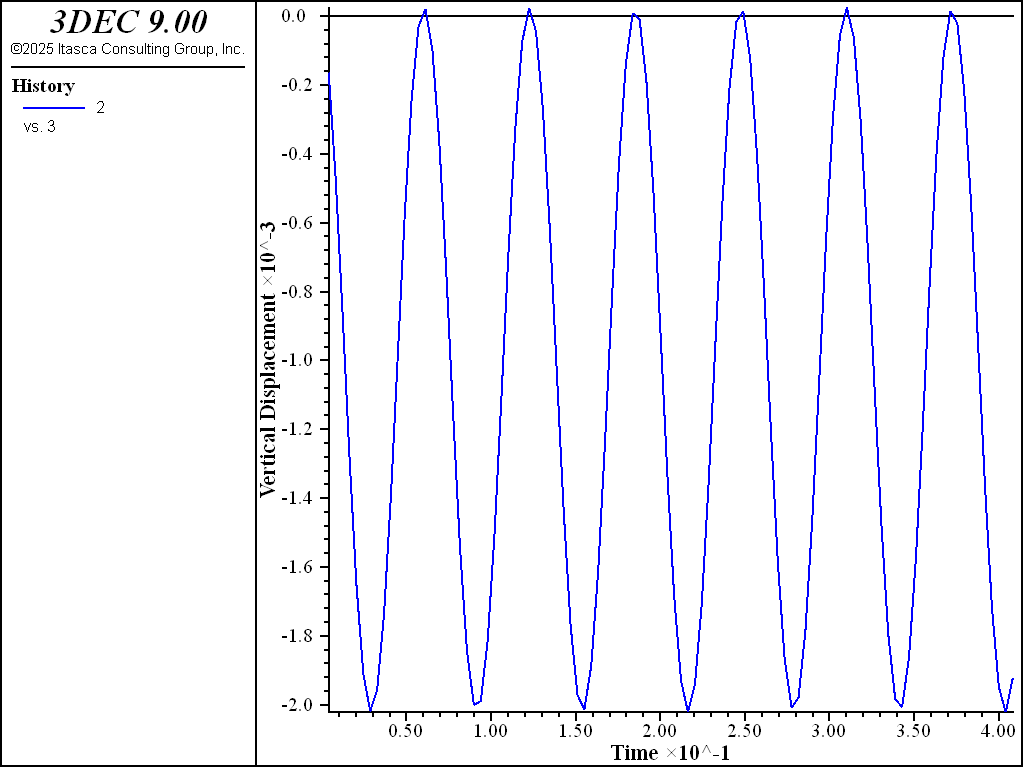
Figure 2: Plot of vertical displacement versus time, for a single block contacting on a rigid base with gravity suddenly applied (no damping).
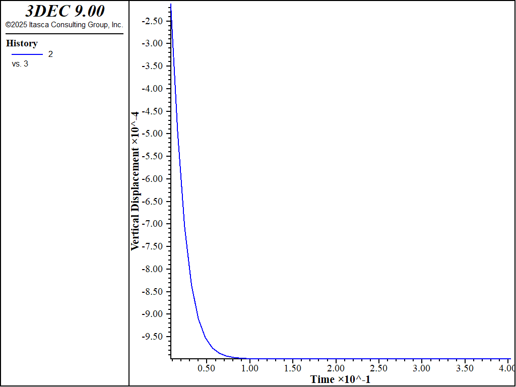
Figure 3: Plot of vertical displacement versus time, for a single block contacting on a rigid base with gravity suddenly applied (mass and stiffness damping).
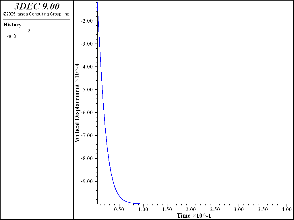
Figure 4: Plot of vertical displacement versus time, for a single block contacting on a rigid base with gravity suddenly applied (mass damping only)
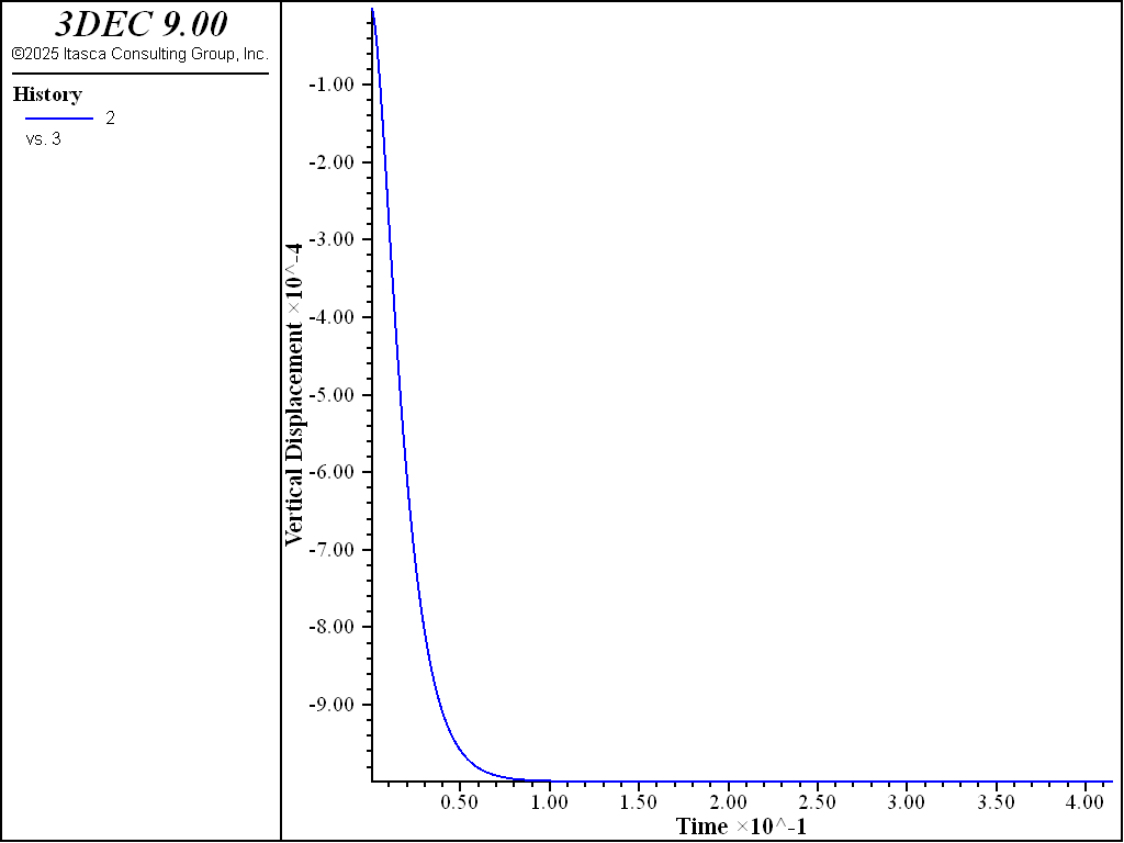
Figure 5: Plot of vertical displacement versus time, for a single block contacting on a rigid base with gravity suddenly applied (stiffness damping only).
Guidelines for Selecting Rayleigh Damping Parameters for Dynamic Analysis
What is normally attempted in a dynamic analysis is the reproduction of the frequency-independent damping of materials at the correct level (e.g., 2-5% for geological materials, and 2-10% for structural systems (Biggs 1964)). Rayleigh damping is frequency-dependent, but has a “flat” region that spans about a 3:1 frequency range, as shown in Figure 1. For any particular problem, a Fourier analysis of typical velocity records might produce a response such as that shown in Figure 6.
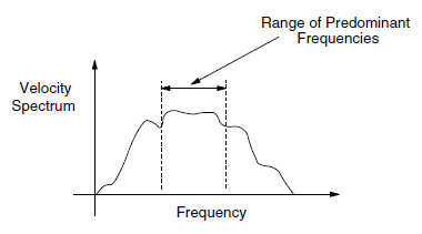
Figure 6: Plot of velocity spectrum versus frequency.
If the highest predominant frequency is three times greater than the lowest predominant frequency, then there is a 3:1 span or range that contains most of the dynamic energy in the spectrum. The idea in dynamic analysis is to adjust \(\omega_{\min}\) of the Rayleigh damping so that its 3:1 range coincides with the range of predominant frequencies in the problem. \(\xi_{\min}\) is adjusted to coincide with the correct physical damping ratio. The predominant frequencies are neither the input frequencies nor the natural modes of the system, but a combination of both. The idea is to try to get the right damping for the important frequencies in the problem.
For some problems involving large movements of blocks, it is improper to use any mass damping because the block motion might be artificially restricted. Examples of such problems include any problems involving free flow or fall of blocks under gravity, and impulsive loading of blocks due to explosions. In such cases it may be appropriate to use only stiffness-proportional damping.
The stiffness-proportional component of Rayleigh damping does affect the critical timestep for the explicit solution scheme in 3DEC. The controlling timestep, therefore, will be reduced as the stiffness damping component is increased (see Belytschko 1983). For problems involving free fall and “bounce” of blocks from a fixed base, the coefficient of restitution is required for accurate modeling. Onishi et al. (1985) provide a method for estimating stiffness damping parameters based on the coefficient of restitution.
Maxwell Damping
Maxwell damping provides an alternative to Rayleigh damping for time-domain seismic deformation analyses. The numerical calculation time using Maxwell damping can be a small fraction of that required for Rayleigh damping. Maxwell damping makes practical large 3-D site response and soil-structure interaction analyses.
Using Rayleigh damping, a target damping ratio can obtain at two specific frequencies; the resulting damping is slightly smaller than the target damping ratio when the frequency is within the range bounded by these two specific frequencies, while damping becomes dramatically larger outside of this range. While Rayleigh damping is helpful to reduce artificial numerical high frequency noise, it can also over damp high frequency content because the damping ratio of the Rayleigh scheme can be more than 20% at high frequencies, even if it is low in the frequency range of interest. As pointed out by Hall (2006), the mass-proportional component of Rayleigh damping is essentially a non-physical mechanism and the stiffness-proportional component for softening materials can result in unrealistically large damping forces under certain conditions. Hall (2006), thus, suggested eliminating the mass-proportional damping contribution and bounding the stiffness-proportional damping contribution for Rayleigh damping. Another serious drawback of Rayleigh damping is the drastically reduced numerical time step. The stiffness damping component of Rayleigh damping leads to increasingly stiff response at higher frequencies, so that a smaller numerical time step is needed for stable numerical integration (Belytschko 1983). For large 3-D models with many degrees of freedom, the requirement of significantly longer machine calculation time makes the applications of the stiffness-proportional Rayleigh damping less practical.
Bielak et al. (2011) and others have shown that an improved form of damping for time-domain analyses can be developed by replacing the dashpot of stiffness damping, with one or more Maxwell components (a spring in series with a dashpot). While each Maxwell component produces frequency dependent damping, peaking at a particular frequency, a number of Maxwell components acting in parallel can be used to produce relatively constant damping over a desired frequency range. Dawson and Cheng (2021) implemented a practical Maxwell damping scheme with three components to provide small strain damping for time-domain seismic deformation analyses. It has been showed (Dawson and Cheng, 2021; Cheng and Dawson, 2022) that this scheme with three Maxwell components can produce relatively constant damping in the frequency range of interest for most seismic deformation analyses. Damping drops off gradually outside of this range.
Formulation
Standard Linear Solid
The basic building block of the Maxwell damping scheme is what is known as the Standard Linear Solid (SLS) as shown in Figure 7. This consists of a primary spring acting in parallel with a single Maxwell component – the Maxwell component itself being a spring in series with a viscous dashpot. Note that the stiffness of the Maxwell component spring is specified here as a fraction of the stiffness K of the primary spring.
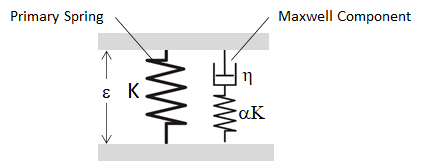
Figure 7: Standard Linear Solid, consisting of a primary spring in parallel with a Maxwell component (a spring in series with a viscous dashpot).
We first derive an expression for the complex (frequency domain) stiffness of the Maxwell component only. The differential equation describing the stress-strain response of the Maxwell component is:
where \(\alpha K\) is the spring stiffness and η is the viscosity. This differential equation can be solved by Fourier transform, or equivalently, by assuming harmonic motions of the form:
where \(\omega\) is the circular frequency and \(\varepsilon_0\) and \(\sigma_0\) are complex amplitudes, accounting for phase as well as magnitude. The complex stiffness, or modulus, of the Maxwell component is then
where
is the relaxation time, the ratio of viscosity to elastic stiffness. Dividing relation (2) by the stiffness K of the primary spring and using (3), results in the normalized, non-dimensional complex modulus for the Maxwell component
Next, consider the complex modulus of the Standard Linear Solid (Figure 7). Since the primary spring and the Maxwell component act in parallel, the stiffness of this system is simply the sum of the individual stiffnesses. The normalized complex modulus is then
or
The damping ratio for a viscoelastic material can be computed from the ratio of the imaginary and real parts of the complex stiffness (Bland, 1960), so that for the Standard Linear Solid, the damping ratio is:
It can be shown that maximum damping occurs at a circular frequency of
with a maximum damping value of
The damping versus frequency response of the SLS is illustrated in Figure 8 which shows the damping ratio for an SLS with 5% damping with a peak frequency of 3.5 Hz. The damping of the SLS has a narrow peak and broad tails.
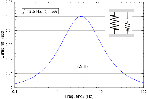
Figure 8: Damping ratio versus frequency for a Standard Linear Solid with a center frequency of 3.5 Hz and a peak damping of 5%.
Full Maxwell Damping Scheme
Next, we consider the full Maxwell damping scheme with three Maxwell components placed in parallel with the primary spring, as shown in Figure 9. Here the primary spring represents the elastic stiffness of the base constitutive model to which damping is to be added.

Figure 9: Maxwell damping scheme where three Maxwell components act in parallel with the primary spring.
According to Equation (4), the normalized complex stiffness of an individual Maxwell component with index k is
where
The normalized complex stiffness of the system as a whole, with a primary spring and three Maxwell components acting in parallel is then
and the damping ratio of the system is
With careful selection of the properties for the three Maxwell components, damping of the system can be made almost constant over a wide frequency range, as shown in Figure 10. Using three Maxwell components, relatively constant damping can be obtained between 0.5 Hz and 25 Hz, the relevant frequency range for most seismic deformation analyses. Outside this range, damping drops off gradually.
It can be seen in Figure 10 that damping of the system as a whole is approximately the superposition of the damping of the individual Maxwell components. This rough approximation provides a helpful starting point for selecting frequencies and damping values for the components to match a target damping value. Damping of the components can then be adjusted to obtain a closer fit. Figure 10 illustrates that this superposition is only approximate, as the peak damping for the 25 Hz component exceeds the damping of the combined system. In fact, there is interaction between the three components, as would be expected from Equation (6).
The lower damping at high frequencies shown in Figure 10 might be seen as a drawback of this technique, as time-domain numerical analyses can be subject to high-frequency numerical noise. However, high frequency vibrations, by definition, experience more cycles per unit time, with each cycle dissipating energy according to the damping ratio. Thus, high frequency noise can be damped out rapidly (in time) with even a very small damping ratio.
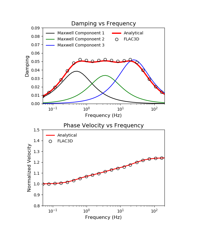
Figure 10: Damping ratio versus frequency for Maxwell damping scheme with three components: System damping, and damping of individual components.
User Inputs and Maxwell Component Properties
For specifying input properties for the damping scheme, it is convenient to think of the system as composed of three SLS, each consisting of a Maxwell component in parallel with the primary spring. Damping of the complete system is then very roughly the superposition of the damping of each of these SLS system. Convenient input parameters for the damping scheme are the center frequencies \(f_k\) (in hertz) of each SLS and the damping ratios \(\xi_k\) of each SLS. The \(\alpha_k\) constants can then be computed from the damping ratio with Equation (5), using the quadratic formula
The relaxation time for the individual Maxwell components is then
and the dashpot viscosities are
If pairs of \((f_k,\xi_k)\) are known, the closed-form solution for the target damping ratio can be straightforwardly obtained. However, calibration requires working in the opposite direction - finding pairs of \((f_k,\xi_k)\) that produce a suitable target damping ratio. A practical guideline is suggested here:
Select a target damping ratio, e.g., 5%.
Estimate a target frequency range over which the approximate target damping ratio is desired. The lower and upper bounds of this range is \(f_1\) and \(f_3\). Then \(f_2\) can be a value so that \(f_2 \approx \sqrt{f_1 f_3}\). For example, if we wish a target damping ratio of 0.05 and constant damping in the range of 0.5 and 25 Hz, then \(f_1\), \(f_2\), \(f_3\) can be 0.25, 3.5, 25 Hz, respectively. Generally, the frequency range of interest should cover the first primary natural frequency of the soil profile, the third primary natural frequency of the soil profile, and the dominate frequency of the input motion.
Using a plotting tool (e.g., Excel), adjust \((\xi_1,\xi_2,\xi_3)\) to approximate the target damping ratio over the target range. Experience has shown that with only a few trails, a satisfactory target damping ratio can be obtained.
Table 1 lists Maxwell component properties for various damping values, all fits using the same set of center frequencies. The resulting damping versus frequency curves are shown in Figure 11. Note that other values can be assigned to the center frequencies \(f_k\) in order to change the position or shape of the damping versus frequency curve.
Maxwell Component Properties |
|||
|---|---|---|---|
Damping |
\(f_1=0.5\) Hz |
\(f_2=3.5\) Hz |
\(f_3=25\) Hz |
\(\xi_1\) |
\(\xi_2\) |
\(\xi_3\) |
|
0.5% |
0.0039 |
0.0029 |
0.0041 |
1.0% |
0.0080 |
0.0060 |
0.0085 |
2.0% |
0.0160 |
0.0120 |
0.0180 |
3.0% |
0.0235 |
0.0190 |
0.0284 |
4.0% |
0.0311 |
0.0260 |
0.0398 |
5.0% |
0.0385 |
0.0335 |
0.0520 |
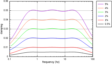
Figure 11: Damping ratio versus frequency for various Maxwell damping values.
Implementation
To provide low strain damping for linear elastic, as well as elasto-plastic constitutive models. Maxwell damping has also been implemented for structural elements such as beams, shells, cables and piles. The incremental equation describing the stress-strain response of a Maxwell component is:
where \(\Delta \varepsilon\) and \(\Delta t\) are known variables based on the 3DEC dynamic implementation scheme. \(\sigma^n\), which is the stress of the Maxwell component calculated in the previous step, n, is also known. In order to calculate the stress of the Maxwell components in the current step, n+1, explicit or implicit algorithms can be employed.
Explicit Algorithm
If \(\sigma=\sigma^n\) in Equation (18), it can be shown that
The time step required for numerical stability is \(\Delta t < 2 \eta / \alpha K\).
Implicit Algorithm
If \(\sigma=\sigma^{n+1}\) in Equation (18), it can be shown that
This algorithm is unconditionally stable. Even if \(\Delta t \to +\infty\), \(\sigma^{n+1}\) is still convergent to a bounded value \(\eta \dot{\varepsilon}\). Thus, the time step for integration of the Maxwell component does not have to be smaller than the time step used for the element dynamic integration. The implicit algorithm, Equation (20), is used for the 3DEC implementation (Dawson and Cheng, 2021). For solid elements, the actual implementation considers as a stress tensor, as a strain tensor and K as a constitutive stiffness matrix. For structural elements K is the element stiffness matrix.
Verification Problem
The following example demonstrates how Maxwell damping works in 3DEC.
| Was this helpful? ... | Itasca Software © 2024, Itasca | Updated: Nov 12, 2025 |
