Power Law Creeping Joint Model In 3DEC
The creep behavior in a discontinuity is of a different nature depending on the joint surface (planar or rough) and on the filling material.
Two mechanisms can be distinguished in unfilled discontinuities, depending on the joint surface characteristics. In planar joints, the creep displacement is controlled by an adhesion-frictional mechanism [Bowden and Curran 1984]. In rough joints, it is due to stress concentrations at asperities that cause slip as the asperities yield progressively and the shear stresses are redistributed to other intact asperities [Schwartz and Kolluru 1982, Ladanyi 1993].
Rock joints may naturally be filled with frictional or cohesive material, which is usually of a poor quality. In this case, the creep is controlled by the characteristics of the filling material [Höwing and Kutter 1985, Malan et al. 1998].
To simulate creep due to the filling material, we propose an adaptation of Norton’s law — commonly used to model the creep behavior of soft rocks subjected to a shear load — for the joint elements.
Formulations
The Power Joint Model in 3DEC is characterized by a visco-elasto-plastic behavior in the shear direction and an elasto-plastic behavior in the normal direction. The visco-elastic and plastic elements are assumed to act in series. The visco-elastic behavior corresponds to a Norton’s law and the plastic behavior corresponds to a Mohr-Coulomb model.
The contact visco-elastic displacement increments are used to calculate the trial force increments. The normal force increment, taking compressive force as positive, is
and the shear force vector increment is
where |
\(K_n\) and \(K_s\) |
are the normal and shear stiffnesses, |
\(A_c\) |
is the contact area, and |
|
\(\Delta U^n\) and \(\Delta \mathbf{U}^s\) |
are the incremental normal and shear displacements. |
Similar to the Norton power law for zones, a two-component law is used for shear.
where \(\bar{F}^{\, s} = \sqrt{\frac{3}{2}}\left|\mathbf{F}^s\right|\);
where
and \(\bar{\sigma} = \frac{F^s}{A_c}\).
\(A_1\) and \(A_2\) are power-law constants set by the user, \(n_1\) and \(n_2\) are power-law exponents set by the user, and \(\sigma_1^{ref}\) and \(\sigma_2^{ref}\) are reference stresses set by the user.
The shear forces may be limited by specifying cohesion and friction as for the Mohr-Coulomb joint model. Similarly, tensile stresses may be limited by specifying a tensile strength. The Creep joint model may also experience dilation as described for the Mohr-Coulomb joint model.
Summary of Joint Creep Model Parameters
The model parameters associated with the creep joint model are summarized in Table 2. The model is assigned to contacts in 3DEC with the block contact assign jmodel power command.
Parameter |
Description |
SI Unit |
|---|---|---|
|
Joint normal stiffness |
Pa/m2 |
|
Joint shear stiffness |
Pa/m2 |
Cohesion |
Pa |
|
|
Tensile strength |
Pa |
Friction angle |
degrees |
|
|
Dilation angle |
degrees |
|
Residual cohesion |
Pa |
|
Residual tensile strength |
Pa |
|
Residual friction angle |
degrees |
|
Power-law constant \(A_1\) |
– |
|
Power-law constant \(A_2\) |
– |
|
Power-law exponent \(n_1\) |
– |
|
Power-law exponent \(n_2\) |
– |
|
Reference stress \(\sigma_1^{ref}\) |
Pa |
|
Reference stress \(\sigma_2^{ref}\) |
Pa |
Subcontact failure states are the same as for the i Mohr-Coulomb Joint Model.
Example: Direct Shear Test
A direct shear creep test is simulated by developing two different models. The first model includes two rock blocks separated by a power type joint (Figure 1, model “joint”). The second one includes a thin layer of 10 cm representing the filling material between two relatively rigid blocks (Figure 2, model “zone”). The filling material is characterized by the power-mohr model. The two rock blocks are 2.0 (length) × 0.5 (height) × 0.05 m (thickness).
Table 3 shows the properties of the rock mass, the joints, and the filling material used in the direct shear test. The Young’s modulus of the filling material is small compared to that of the rock. The normal stiffness of the joint is chosen so as to reduce the relative displacement between the upper and lower faces of the filling material. Also, the tangential stiffness of the “joint” model is set to a low value compared to the normal stiffness.
The two models are subjected to two loading phases. The models are first confined to a isotropic stress of 2 MPa. Then an additional horizontal stress of 1 MPa is applied on the lateral sides of the upper block (compression on the left side and traction on the right) in the shearing phase. This leads to a shear stress in the contact elements in the model “joint” and a deviatoric stress in the filling material in the model “zone”.
A mechanical calculation without activation of creep is performed. At this point, the initial state of the models is obtained. Then a creep calculation is carried out over a period of 100 years to get the long-term behavior. The displacement is reset to zero before the creep calculation. This makes it possible to dissociate the displacements produced by the loading at short term and those produced by the creep at long term.
The horizontal displacement contours at short term (at the end of the shearing phase) are shown in Figure 3 and Figure 4. The long term displacements (after 100 years) are shown in Figure 5 and Figure 6.
Figure 7 shows the evolution of the shear displacement at the top and the middle of the models over 100 years of creep. The evolution of the shear stress in the same period is also presented in Figure 8. Similar response is observed in the two models.
The shear displacement evolution of the fracture is most likely linear with time.
There is a slight decrease of the shear stress over time.
Parameter |
Unit |
Model “joint” |
Model “zone” |
|---|---|---|---|
Young’s Modulus – rock |
GPa |
40 |
40 |
Poisson’s Ratio – rock |
– |
0.29 |
0.29 |
Young’s modulus – joint fill |
GPa |
– |
4 |
Poisson’s Ratio – joint fill |
– |
– |
0.29 |
Joint normal stiffness |
GPa/m2 |
1x10⁴ |
– |
Joint shear stiffness |
GPa/m2 |
15.5 |
– |
Cohesion |
MPa |
2.3 |
2.3 |
Tensile strength |
Pa |
5 |
5 |
Friction angle |
degrees |
12 |
12 |
Power–law constant \(A_1\) |
? |
1x10-50 |
1x10-50 |
Power–law constant \(A_2\) |
? |
0 |
0 |
Power–law exponent \(n_1\) |
– |
6.8 |
6.8 |
Power–law exponent \(n_2\) |
– |
0 |
0 |
Reference stress \(\sigma_1^{ref}\) |
MPa |
0 |
0 |
Reference stress \(\sigma_2^{ref}\) |
MPa |
0 |
0 |
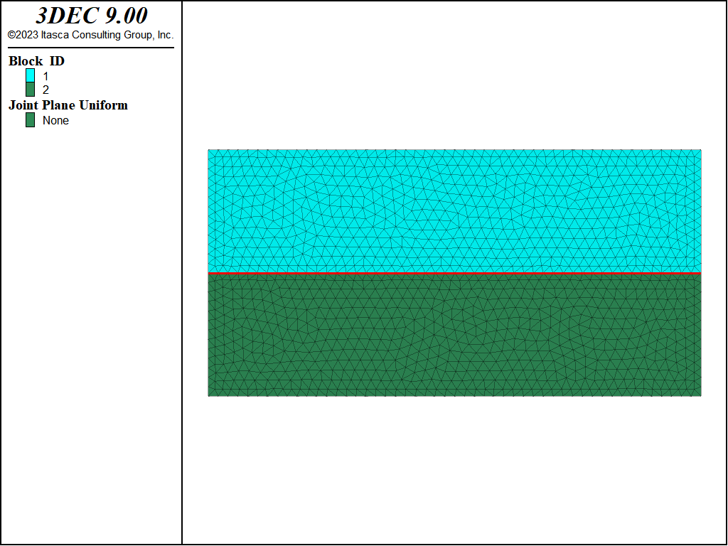
Figure 1: Model with power joint.
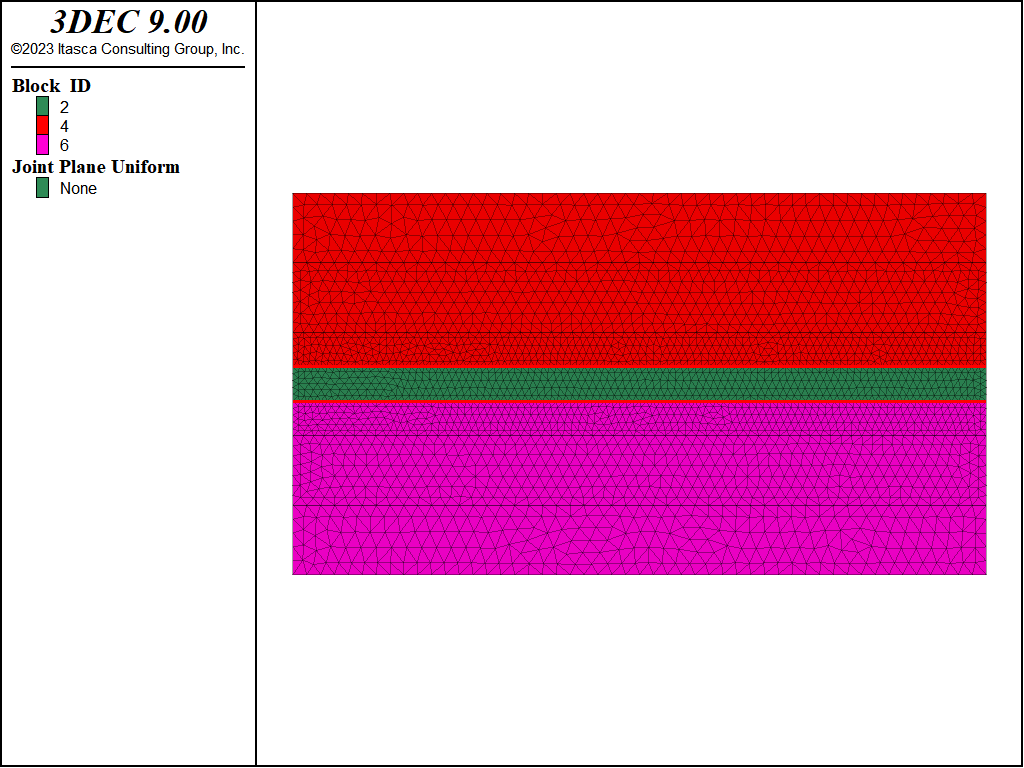
Figure 2: Model with power-mohr infilling material representing the joint.
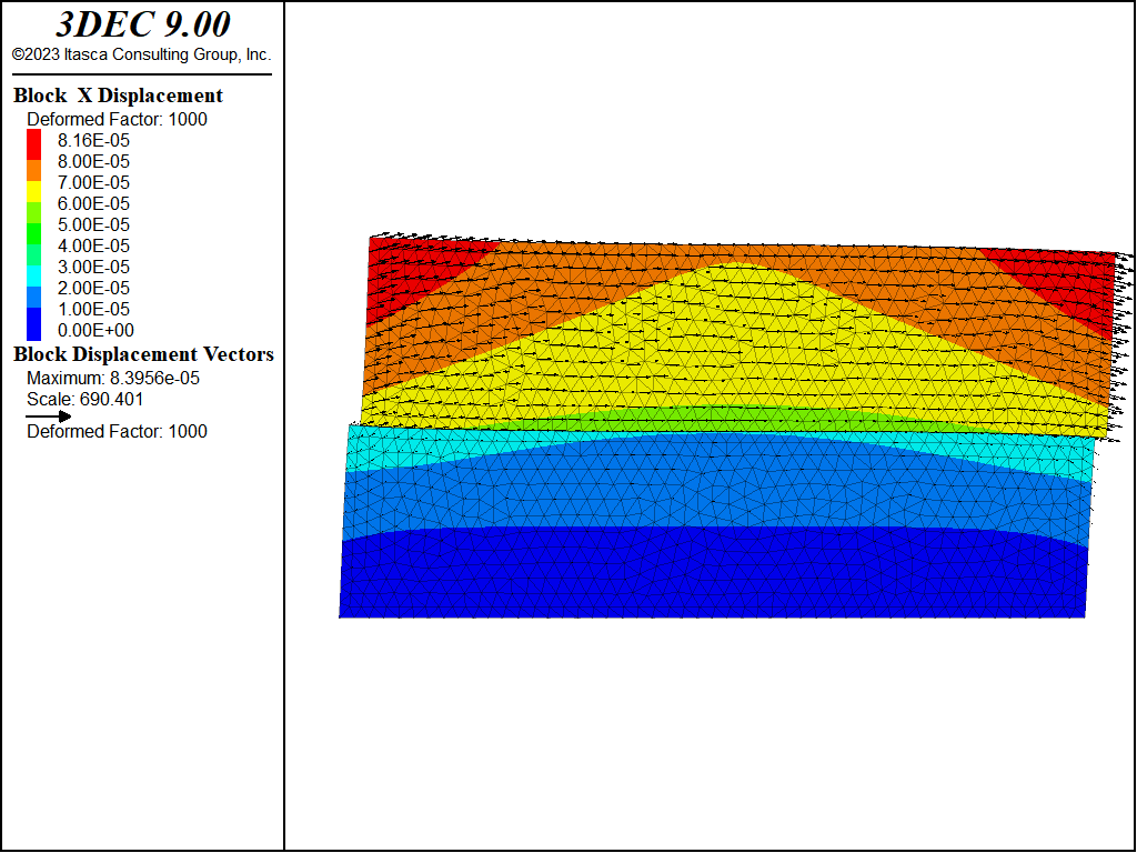
Figure 3: Horizontal displacement at the end of the shearing phase for the “joint” model. Deformations are exaggerated 1000x.
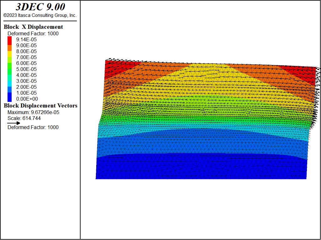
Figure 4: Horizontal displacement at the end of the shearing phase for the “zone” model. Deformations are exaggerated 1000x.
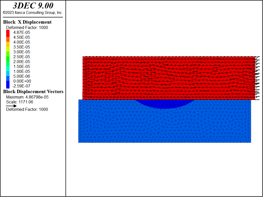
Figure 5: Horizontal displacement after 100 years for the “joint” model. Deformations are exaggerated 1000x.
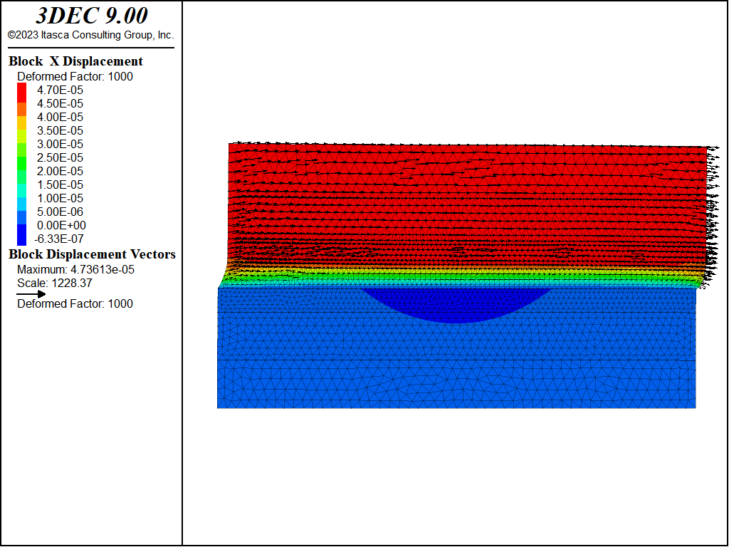
Figure 6: Horizontal displacement after 100 years for the “zone” model. Deformations are exaggerated 1000x.
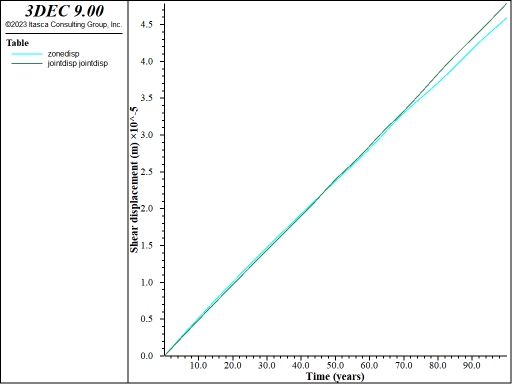
Figure 7: Horizontal displacement evolution over 100 years.
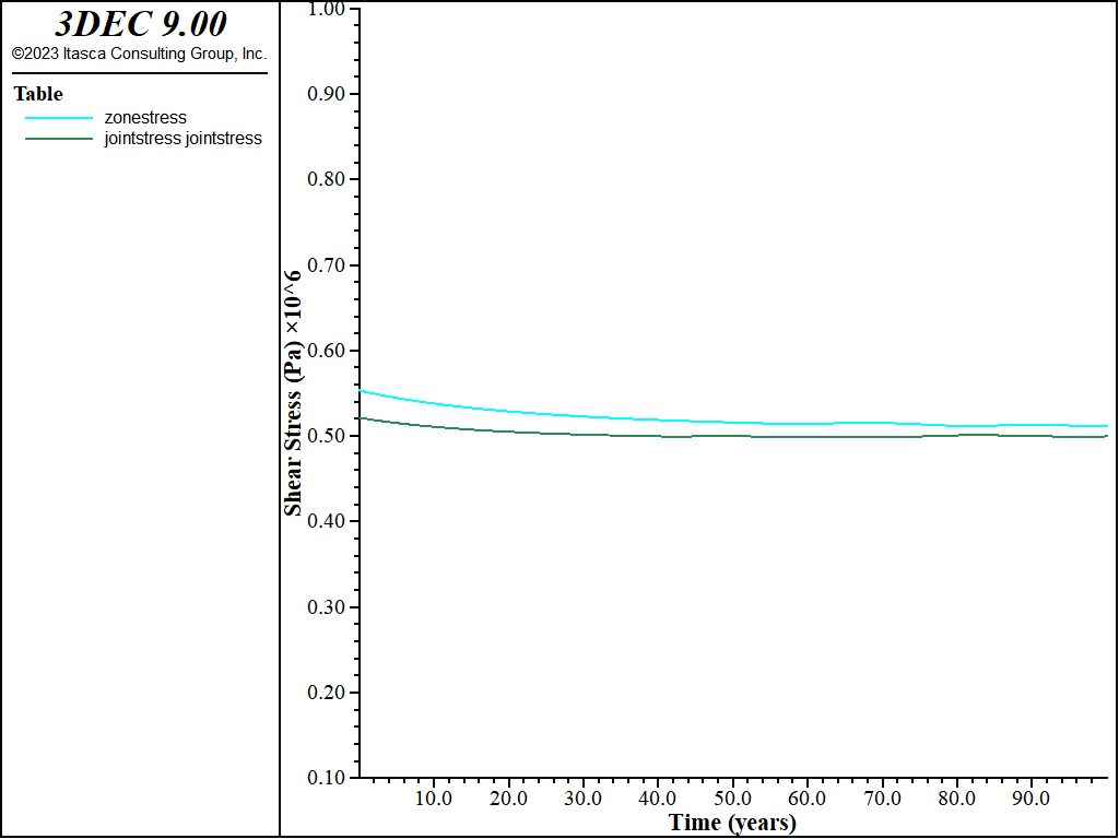
Figure 8: Shear stress evolution over 100 years.
Data Files
Run_Joint.dat
model new
model random 1000
model configure creep

program call "data.dat"
block create brick  [-0.5*_x] [0.5*_x] ...
                    [-0.5*_y] [0.5*_y] ...
                    [-0.5*_z] [0.5*_z] group "Lower"

block cut joint-set dip 0 dip-direction 0 origin 0 0 0
block zone generate edgelength [_edge]

block group "Upper" range position-z [0] [0.5*_z]

model large-strain off
model creep active off

; Mechanical properties
block zone  cmodel assign elastic
block zone property  young    [_E_rock]     ...
                     poiss    [_nu_rock]    ...
                     density  [_dens_rock]
block contact jmodel power
block contact property stiffness-normal [_jkn] stiffness-shear [_jks]    ...
                       cohesion [_jcoh] friction [_jfri] tension [_jten] ...
                       friction-residual [_jfri]                         ...
                       constant-1 [_jpow_a1] exponent-1 [_jpow_n1]

; Initial stress (isotropic 2MPa)
[_refStress = - 2.e6]
block insitu stress [_refStress] [_refStress] [_refStress] 0. 0. 0.

block face apply stress-xx [_refStress]  ...
  range position-x  [-0.5*_x] tolerance 0.001
block face apply stress-xx [_refStress]  ...
  range position-x  [ 0.5*_x] tolerance 0.001
block face apply stress-zz [_refStress]  ...
  range position-z  [ 0.5*_z] tolerance 0.001
block gridpoint apply velocity-y 0.  ...
  range position-y  [-0.5*_y] tolerance 0.001
block gridpoint apply velocity-y 0 range position-y [ 0.5*_y] tolerance 0.001
block gridpoint apply velocity 0 0 0 range position-z [-0.5*_z] tolerance 0.001

model history mechanical ratio
model solve ratio 1e-7

; Initialize displacement and velocities
block gridpoint initialize displacement 0. 0. 0.
block gridpoint initialize velocity 0. 0. 0.
block contact reset displacement
block contact reset state

; Perform shear test (apply 1MPa in the x-direction on upper vertical borders)
block face apply stress-xx [_refStress*0.5]  ...
                 range position-x  [-0.5*_x]  group 'Upper'
block face apply stress-xx [-_refStress*0.5] ...
                 range position-x  [ 0.5*_x]  group 'Upper'

block contact history stress-shear position 0. 0. 0.
block contact history stress-normal position 0. 0. 0.
block contact history displacement-shear position 0. 0. 0.
block history displacement-x position 0. 0. [_z]

data scalar create 0. 0. 0.
model solve ratio 1e-7
model save "joint_static"

=====================================================

model creep active on
; Initialize displacement and velocities
block gridpoint initialize displacement 0. 0. 0.
block gridpoint initialize velocity 0. 0. 0.
block contact reset displacement
block contact reset state

; Creep timestep control parameters
model creep timestep automatic on
model creep timestep minimum 1e-10
model creep timestep starting 1e-10
model creep timestep max 100
model creep timestep latency 50
model creep timestep lower-bound 5.e-6
model creep timestep upper-bound 2.e-5

fish define crtime_years
  crtime_years = creep.time.total/(24.0*365.0)
end

history purge
model history creep time-total
model history creep cycles-total
fish history crtime_years
model history timestep

model solve creep time-total  [365.*24*100.]
model save "joint_creep"

; dump histories forigin comparison with zone model
history export '5' vs '8' table 'jointdisp'
history export '2' vs '8' table 'jointstress'
table 'jointdisp' export 'jointdisp.tab'
table 'jointstress' export 'jointstress.tab'
Run_Zone.dat
model new
model random 1000
model configure creep

program call "data.dat"

[thick_ratio = 0.1]
block create brick  [-0.5*_x] [0.5*_x]          ...
                    [-0.5*_y] [0.5*_y]          ...
                    [-0.5*_z-thick_ratio*_z/2.] ...
                    [0.5*_z+thick_ratio*_z/2] group "Lower"

block cut joint-set dip 0 dip-direction 0 origin 0 0 [ thick_ratio*_z/2.]
block cut joint-set dip 0 dip-direction 0 origin 0 0 [-thick_ratio*_z/2.]

block group "Upper" range position-z [0] [0.5*_z]
block group "Filling material" ...
            range position-z [-thick_ratio*_z/2.]  [thick_ratio*_z/2.]

block hide on range group "Filling material"
block cut joint-set dip 0 dip-direction 0 ...
  origin 0 0 [ thick_ratio*_z/2. + 0.1*_z] join
block cut joint-set dip 0 dip-direction 0 ...
  origin 0 0 [ thick_ratio*_z/2. + 0.3*_z] join
block cut joint-set dip 0 dip-direction 0 ...
  origin 0 0 [-thick_ratio*_z/2. - 0.1*_z] join
block cut joint-set dip 0 dip-direction 0 ...
  origin 0 0 [-thick_ratio*_z/2. - 0.3*_z] join
block hide off

block zone generate edgelength [_edge/2.]   ...
   range position-z [-thick_ratio*_z/2. - 0.1*_z] [thick_ratio*_z/2. + 0.1*_z]
block zone generate edgelength [_edge*0.75] ...
   range position-z [-thick_ratio*_z/2. - 0.3*_z] [thick_ratio*_z/2. + 0.3*_z]
block zone generate edgelength [_edge]

model large-strain off
model creep active off

; Mechanical properties
block zone  cmodel assign elastic
block zone  property  young    [_E_rock]      ...
                      poiss    [_nu_rock]     ...
                      density  [_dens_rock] range group "Filling material" not
block zone cmodel assign power-mohr range group "Filling material"
block zone property   young    [_E_fill]     ...
                      poiss    [_nu_fill]     ...
                      density  [_dens_rock]   ...
                      cohesion [_coh]         ...
                      dilation [_dil]         ...
                      friction [_fri]         ...
                      tension  [_ten]         ...
                      constant-1  [_pow_a1]   ...
                      exponent-1  [_pow_n1] range group "Filling material"

; Joint properties
block contact jmodel assign elastic ...
              property stiffness-normal [_jkn] stiffness-shear [_jkn]

; Initial stress (isotropic 2MPa)
[_refStress = - 2.e6]
block insitu stress [_refStress] [_refStress] [_refStress] 0. 0. 0.

block face apply stress-xx [_refStress]  range position-x  [-0.5*_x]
block face apply stress-xx [_refStress]  range position-x  [ 0.5*_x]
block face apply stress-zz [_refStress]  ...
                        range position-z  [ 0.5*_z+thick_ratio*_z/2]
block gridpoint apply velocity-y 0.  range position-y  [-0.5*_y]
block gridpoint apply velocity-y 0.  range position-y  [ 0.5*_y]
block gridpoint apply velocity 0 0 0 ...
                    range position-z  [-0.5*_z-thick_ratio*_z/2]

model history mechanical ratio
model solve ratio 1e-7

; Shear Static
; Initialize displacement and velocities
block gridpoint initialize displacement 0. 0. 0.
block gridpoint initialize velocity 0. 0. 0.
block contact reset displacement
block contact reset state

; Perform shear test (apply 1MPa in the x-direction on upper vertical borders)
block face apply stress-xx [_refStress*0.5]  ...
  range position-x  [-0.5*_x] tolerance 0.001 group 'Upper'
block face apply stress-xx [-_refStress*0.5] ...
  range position-x  [ 0.5*_x] tolerance 0.001 group 'Upper'

; Compute equivalent shear displacement
fish define get_hist_gp
    gp_upper=block.gp.near(0.,0.,thick_ratio*_z/2)
    gp_lower=block.gp.near(0.,0.,-thick_ratio*_z/2)
    zp_mid = block.zone.near(0.,0.,0.)
    data.scalar.create(block.gp.pos(gp_upper))
    data.scalar.create(block.gp.pos(gp_lower))
end
[get_hist_gp]

fish define sdisp_mid
   sdisp_mid = block.gp.disp.x(gp_upper) - block.gp.disp.x(gp_lower)
   ; deviatoric_stress=principal_stress_tensor-mean_stress_tensor
   sstress_mid = block.zone.stress.xz(zp_mid)
end

; Equivalent shear displacement
fish history sdisp_mid
; Point at the top of the model
block history displacement-x position 0. 0. [_z+thick_ratio*_z/2]
fish history sstress_mid

model solve ratio 1e-7
model save "zone_static"

===========================================

; Creep
model creep active on

; Initialize displacement and velocities
block gridpoint initialize displacement 0. 0. 0.
block gridpoint initialize velocity 0. 0. 0.
block contact reset displacement
block contact reset state

; Creep timestep control parameters
model creep timestep automatic on
model creep timestep minimum 1e-10
model creep timestep starting 1e-10
model creep timestep max 100
model creep timestep latency 50
model creep timestep lower-bound 5.e-6
model creep timestep upper-bound 2.e-5

fish define crtime_years
  crtime_years = creep.time.total/(24.0*365.0)
end

history purge
model history creep time-total
model history creep cycles-total
fish history crtime_years
model history timestep

model solve creep time-total  [365.*24*100.]

model save "zone_creep"

; dump histories to tables and import joint histories for comparison
history export '3' vs '7' table 'zonedisp'
history export '4' vs '7' table 'zonestress'
table 'jointdisp' import 'jointdisp.tab'
table 'jointstress' import 'jointstress.tab'
References
Bowden R K, Curran J H, 1984. Time-dependent behaviour of joints in Shale. In: Dowding C H, Singh M M (eds). Rock mechanics in productivity and production: proceedings of the 25th U.S. Symposium on Rock Mechanics, Northwestern University, Evanston, Illinois, 25–27 June 1984. Littleton: Society of Mining Engineers, pp 320–327.
Höwing K D, Kutter H K, 1985. Time-dependent shear deformation of filled rock joints: a keynote lecture. In: Stephansson O (ed). Fundamentals of rock joints: proceedings of the international Symposium on Fundamentals of Rock Joints, Björkliden, Sweden, 15–20 September 1985. Luleå: CENTEK, pp 113–122.
Ladanyi B, 1993. Time-dependent response of rock around tunnels. In: Fairhurst C (ed). Comprehensive rock engineering: principles, practice & projects. Vol. 2, Analysis and design methods. Oxford: Pergamon, pp 77–112.
Malan D F, Drescher K, Vogler U W, 1998. Shear creep of discontinuities in hard rock surrounding deep excavations. In: Rossmanith H-P (ed). Mechanics of jointed and faulted rock: proceedings of the third International Conference on Mechanics of Jointed and Faulted Rock – MJFR-3, Vienna, Austria, 6–9 April 1998. Rotterdam: Balkema, pp 473–478.
Schwartz C W, Kolluru S, 1982. The influence of stress level on the creep of unfilled rock joints. In: Proceedings of the 25th U.S. Symposium on Rock Mechanics, pp 333–340.
| Was this helpful? ... | Itasca Software © 2024, Itasca | Updated: Nov 12, 2025 |
