Sketch (formerly Extrude)
Note
Starting with v9.0, operations formerly called “extrusion” have been renamed “sketch”. This name more accurately describes operations in both FLAC2D and FLAC3D. Correspondingly, commands and FISH functions now begin with sketch instead of extrude. For example, see sketch set select or sketch.block.group.
A sketch is a 2D geometric design of a model that can be created interactively (see i Sketch Tool). For FLAC2D, zones are directly created from a sketched design (termed a set). For FLAC3D, an additional extrusion step is required to first extrude the design in the third dimension and then create FLAC3D zones. Multiple sketch sets can be created, each under a different name, but at any time only one c set is active. Commands on objects in a set (c blocks, c points, c edges, c segments) apply to the objects in the currently active set (see sketch set select); c mesh commands apply to all sets.
The process to create a set is sequential. Points are created in space, then connected by edges, which are themselves closed into blocks. Edges may be either linear or curved. Curved edges follow a path given by control points.
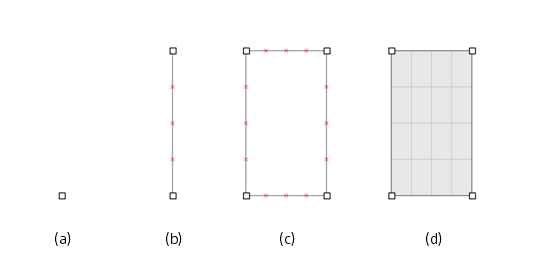
Figure 1: A sketch is made by creating points (a), from which edges are built (b). With additional edges, closed shapes may be defined (c). On an edge, the red marks indicate expected zoning. Once a shape is closed, it may be specified as a block (d), at which point its mesh is defined.
Two block types may be created in a sketch: simple blocks with structured mesh or blocks with unstructured mesh. Blocks of the simple type — referred to as “regular” blocks — are typically three- or four-sided blocks. Blocks with unstructured mesh — “irregular” blocks — may have convex or concave boundaries, may be multiply-connected, and/or may contain nested blocks).
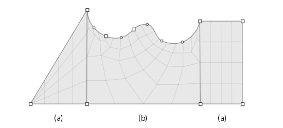
Figure 2: A sketch that combines (a) regular blocks of three and four sides, with structured meshing, and (b) an irregular block with unstructured mesh. The upper side of the center block is composed of three curved edges; curvature is achieved by placement of the round control points; an edge may contain multiple control points.
Structured and unstructured meshes both consist of triangular and/or quadrilateral elements. For FLAC2D, a single triangular or quadrilateral zone is created from each mesh element when zone generate from-sketch is used. Similarly, in FLAC3D, after extrusion parameters are specified the zone generate from-sketch command will create a single brick- or wedge-type zone from each element of the mesh.
Zoning of a block—whether regular or irregular—is typically determined by parameters set on block edges. Note there are also auto-zoning facilities that can perform zoning on the entire model in one go. Edge assignments propagate across all blocks attached to the edge.
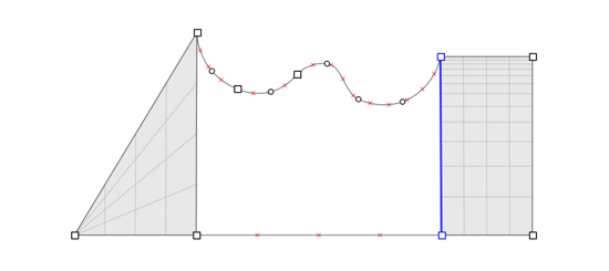
Figure 3: Parameters on the highlighted edge are changed — the number of zones along the edge is increased and a ratio is specified. For the structured block, the changes and rezoning are applied automatically; the changes cause the previous zoning in the unstructured block to be “erased”, and new zoning must be calculated.
There are variances between edge parameter assignments and modifications for the two block types.
Regular blocks
a ratio may be specified to refine zoning along an edge
a multiplier factor can be assigned to a regular block to increase (densify) the number of zones in it
a change to an edge parameter is automatically applied to the block’s mesh
a zoned block may be split, with automatic propagation of the split across attached blocks
Irregular blocks
the number and ratio parameters are unique for every edge in the block
on any change of the edge parameters, including vertex locations, any existing mesh is erased and a new unstructured mesh must be created
multipliers are not accepted and splitting is not available
An unstructured mesh is generally easier to construct and less geometrically stringent. A fully structured mesh, by contrast, must be constructed entirely of three- and four-sided blocks; conforming to this constraint requires greater effort and attention in construction. However, structured meshes have advantages: they may be exported for further refinement to the i Building Blocks workspace; and, structured meshes are easier to refine at specific areas of interest within the mesh, using either ratios on edges, block splitting, or both.
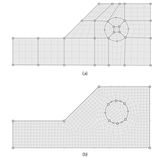
Figure 4: A simple example slope with a circular tunnel constructed of 18 regular four-sided blocks comprising a fully structured mesh (a) and the same constructed of two irregular blocks with unstructured mesh, where the tunnel block is nested in the slope block (b).
Groups can be assigned to points, edges, and blocks in a sketch set, which are then assigned to the gridpoints, faces, and zones derived from them.
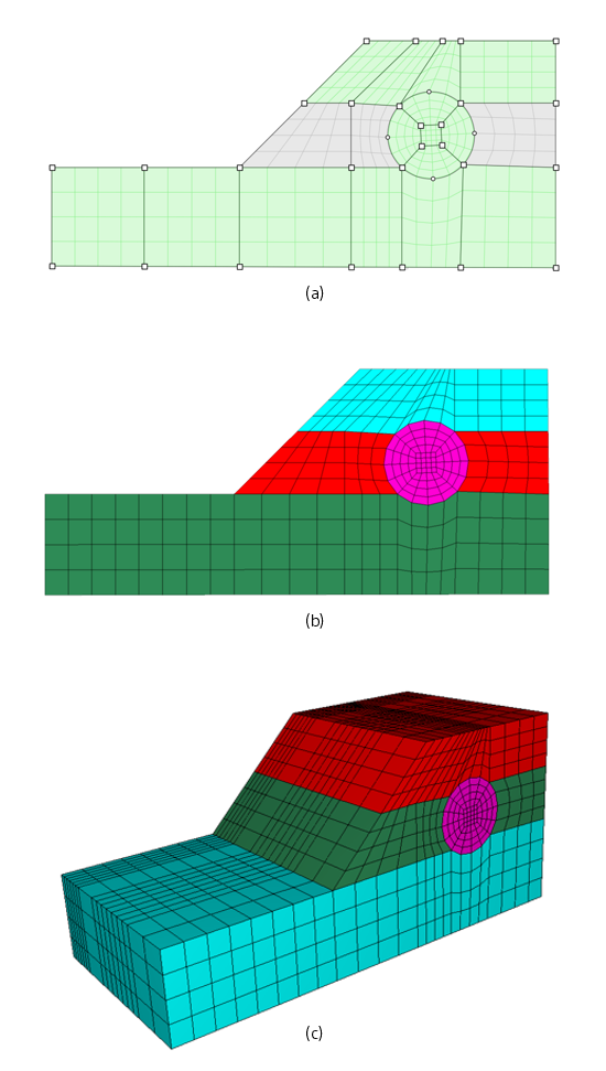
Figure 5: A sketch partitioned into groups, highlighted green (a), produces zones in a FLAC2D model (b) or in a FLAC3D model (c) that have group assignments that correspond to the sketch group assignments.
Sketches are easiest to create interactively in the i Sketch tool. Operations performed with the tool emit commands as the sketch is constructed. These commands are described in Commands; FISH functions for working with sketches are detailed in FISH Functions. The availability of both make it possible to construct models in FLAC from sketch commands without use of the i Sketch tool—that is, directly from a data file.
Sketch Workspace
The Sketch workspace provides interactive tools for drawing and meshing 2D models and (if working in FLAC3D) extruding them into a third dimension.
Each “sketch” is created within a separate sketch set; a modeling project may contain multiple sets.
The tool provides two different model views. The construction is used to draw and mesh the 2D section. The extrusion view, in FLAC3D, is where the extent, shape, and meshing of the extrusion are defined.
A finished 2D sketch generates model zones directly. A finished 3D sketch, depending on its makeup, may take a couple of paths: if fully structured, it may be exported to the Building Blocks workspace for further modifications; or it may be generated into zones and viewed in the Model workspace.
Operations in the Sketch workspace are automatically translated into commands that are sent to the i Console pane. See the command reference for information on command syntax ( Extrude Commands , Extrude FISH ).
In This Section
This section describes working with sketches in four major subsections. The first walks through the sketch workspace workflow for building a sketch and generating zones from it. The second considers supplemental facilities in the workspace (grouping, automatic zoning) and other rudimentary aspects of the workspace (object selection, setting object properties, etc.). The third section provides a reference for all sketch commands, and the last section describes all sketch FISH functions.
| Was this helpful? ... | Itasca Software © 2024, Itasca | Updated: Nov 12, 2025 |
