FLAC3D Theory and Background • Interfaces
Modeling Guidelines
Troubleshooting
The geometry of the model should be checked after the grid has been generated and the interface elements added, but before the grid is modified to bring the faces into contact. The “zone” plot item should be combined with the “interface” plot item, given with a different color, to show that interface elements have been placed on the right surfaces.
After the two sides of the interface have been brought into contact, execute a model step
0 command to calculate contact locations. The zone interface i
list information command should be given to list the target faces for all nodes in
contact on interface i, along with the weighting factors for distribution of forces to
the target face. During the calculation process, the “interface” plot item colored by normal
stress or shear stress can be used to monitor the development of shear and normal stresses along
the interface. Note that interface property values will default to zero if not given.
For example, zero normal stresses may indicate that the normal stiffness was not specified.
Initial Stresses
Interface stresses will not be initialized automatically when stresses are initialized in the
grid (with the initialize-stresses keyword). The
zone interface node initialize-stresses commands can be used to initialize the interface
normal stress and shear stress vector components. Alternatively, the model containing interfaces
can be stepped to an initial equilibrium state; displacements may be set to zero after the
initial state is reached.
Interface Corners
Pay special attention to interfaces that will result in sharp corners (see Figure 1). The interface node at the corner has a representative area that is twice the value that is actually in contact. If only the bottom surface is to come into contact (as indicated in the figure), then only that surface should have interface elements applied. If both surfaces will come into contact, two separate interfaces should be specified.
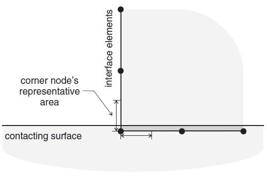
Figure 1: Effective area at an interface corner.
There is a separate problem for interior corners (see Figure 2). In this case, the interface elements could be placed either on side A (facing into the corner) or side B (facing away from the corner). If the elements are placed on side A, then the corner node will move into an area that is not “behind” the faces on either side, and a contact will not be detected. Instead, the interface elements should be placed on side B. Additionally, two different interfaces should be created for the two edges of the corner, as described in Figure 1.
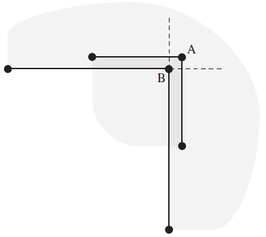
Figure 2: Interface at an interior corner.
Overlapping Interfaces
Interface nodes can only register contact with one face at a time. This can cause problems in the areas of multiple intersecting interfaces (see Figure 3). Interface node A on the bottom surface will register contact with either target face b or face c. The order in which the interfaces are specified, or the effect of rounding off, determines this. This means that either gridpoint B or C will not register an appropriate contact and resisting force, causing arching at the interface connection. One solution is to declare two interfaces facing each other, each with half the stiffness and strength of the whole; another is to increase the number of interface nodes in that area. Either of these solutions will reduce the problem, but may not eliminate it.
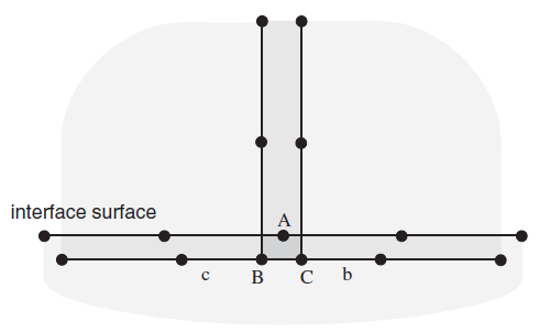
Figure 3: Intersection of overlapping interfaces.
Interfaces and Fluid Flow
The complete interaction of a fluid with an interface is not modeled. Fluid may flow across an
interface in the normal direction without resistance, provided that the two surfaces are in
contact; flow within the interface (in the parallel direction) is not modeled. The
zone interface i permeability = on/off command can be used to
turn this option on or off in interface i (the default is on). If
model configure fluid is invoked, changing the interface element size by specifying the
maximum-edge keyword with the zone interface element command will automatically
make the interface impermeable, even if the keyword permeability = on has been
issued. Do not specify maximum-edge if flow across the interface is desired.
The fluid pressure at interface nodes may be used to determine the effective stress for the purpose of computing slip or tensile failure conditions, but the fluid does not exert any mechanical force on the sides of the interface. The zone interface i effective = on/off command may be used to work in effective or total stress, respectively, for interface i (the default is on). There is no coupling between joint movement and volume changes in the fluid.
Interfaces and Changing Interacting Objects in Small Strain
Interfaces operating in small-strain mode derive their forces from a comparison of “virtual positions” of the two interacting faces, where a virtual position of a point is the original coordinate of the point plus the accumulated displacement (displacement-small) to date. If one contacting object is removed (e.g., backfill within a tunnel), and another substituted (e.g., a liner is installed) using the same interface, then large initial stresses may appear because the two sides of the interface appear to interpenetrate, because the virtual position of the old object has changed with respect to the specified position of the new object.
The stored displacements associated with a particular interface n may be multiplied by a
factor v, using the keyword displacement-small combined with the
zone interface node command. Normally, this factor will be zero, thus restoring the
virtual positions of the faces making up the interface “host” to their original locations. In
this case, a new interacting object will not cause initial stresses to be generated when its
coordinates match the original coordinates of the interface host faces. However, it is possible
to give v a nonzero value, in order to simulate an initial lack-of-fit between the two
contacting objects.
| Was this helpful? ... | Itasca Software © 2024, Itasca | Updated: Nov 12, 2025 |
