FLAC3D Theory and Background • Factor of Safety
Failure of a Slope with a Complex Surface Profile in a Mohr-Coulomb Material
Problem Statement
Note
The project file for this example is available to be viewed/run in FLAC3D. The project’s main data file is shown at the end of this example.
This example illustrates the ability of FLAC3D to identify the critical failure state of a slope with a complex surface profile (i.e., a slope profile defined by more than one inclination). The slope in this exercise is composed of two inclinations: a 45° inclination in the lower part and a 26.7° inclination in the upper part. The slope geometry is shown in Figure 1. The problem conditions are taken from Cheng et al. (2007). Cheng et al. determine five local minima failure surfaces for this slope using the Morgenstern-Price limit equilibrium method, as shown in Figure 2. They identify two possible critical failure surfaces from a series of limit equilibrium simulations: one at a factor of 1.383 and one at 1.3848.
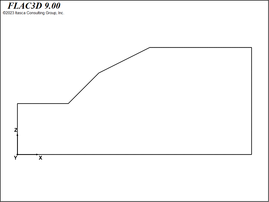
Figure 1: Slope with complex surface profile.
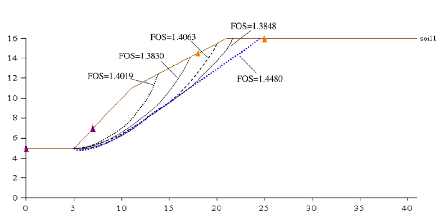
Figure 2: Local minima failure surfaces and factors of safety calculated by limit equilibrium method (from Cheng et al. 2007).
The material properties of the slope material in this problem include the following:
Elastic modulus, \(E\) |
= |
14.0 MPa |
Poisson’s ratio, \(ν\) |
= |
0.3 |
Unit weight, \(γ\) |
= |
20.0 Kn/m3 |
Cohesion, \(c\) |
= |
10 kPa |
Friction angle, \(ϕ\) |
= |
30° |
Dilation angle, \(ψ\) |
= |
0.0 |
Tensile strength, \(σ_t\) |
= |
\(c\) /tan \(ϕ\) |
FLAC3D Model
The FLAC3D model is constructed based upon the problem dimensions given by Cheng et al. (2007). The slope geometry is oriented in the \(x\)-\(z\) plane and is one zone thick in the \(y\)-direction. The model geometry is shown in Figure 3. Simulations were made with progressively finer zoning in order to determine the mesh size that provides the most accurate solution. The calculated factor of safety decreases as the mesh size is decreased, leveling off at a mesh created for 144 zones in the horizontal direction.
Gravity is applied, and the model is solved to an equilibrium state to establish the initial stresses in the model. Note that some isolated zones have reached a shear failure state at this stage, as indicated in theplasticity state plot shown in Figure 4. The slope is stable.
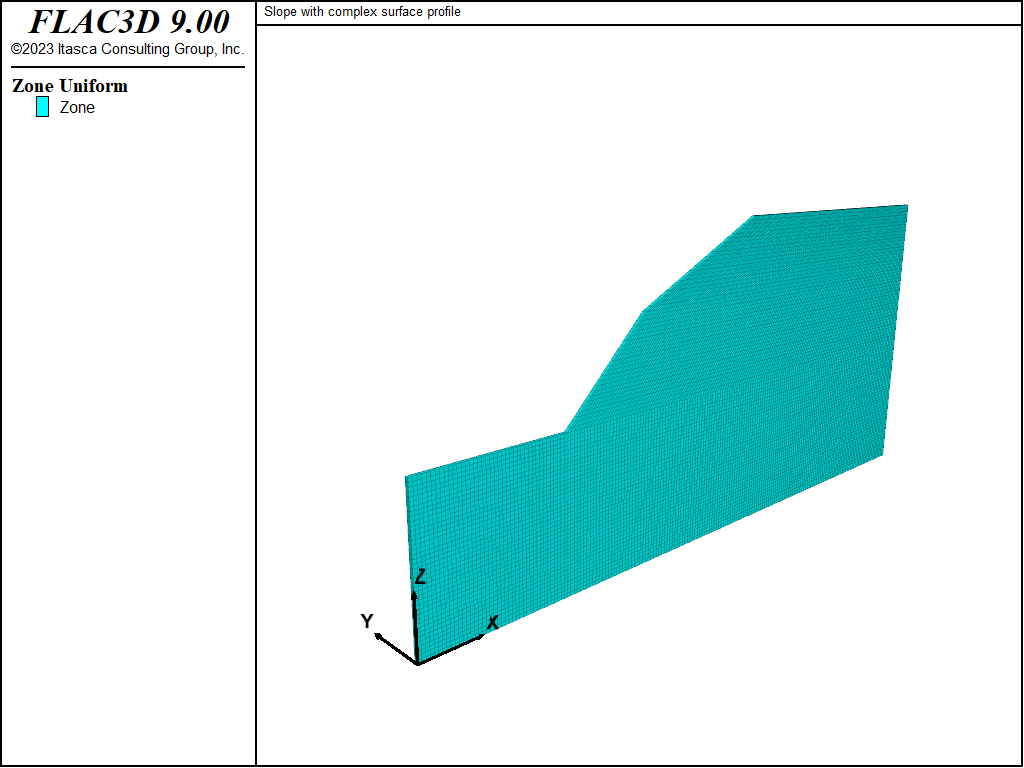
Figure 3: Slope model geometry.
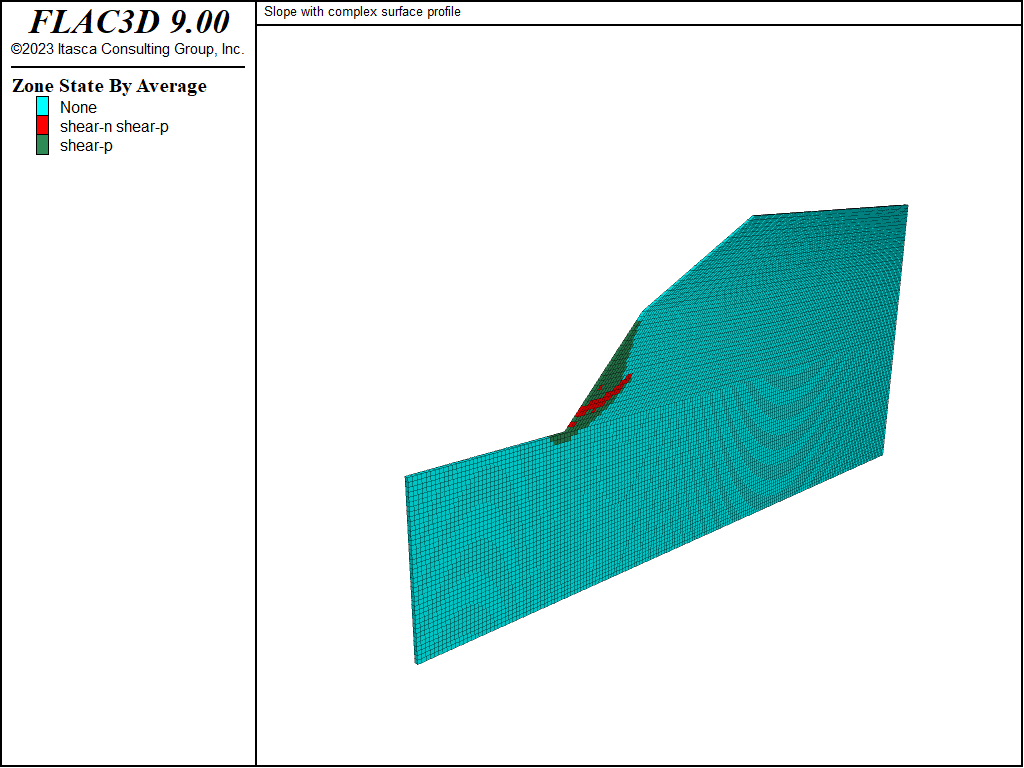
Figure 4: Plasticity state in slope at initial force equilibrium.
The factor of safety calculation time can be reduced by selecting lower-bound and upper-bound bracketing values that are close to the actual safety factor. Based upon the range of factors shown in Figure 2, the lower-bound bracketing factor is set to 1.30 and the upper-bound to 1.45. The bracketing factors are set with bracket, an optional keyword to the model factor-of-safety command.
The calculated factor of safety is 1.38 and the failure surface develops as defined by a shear-strain contour plot shown in Figure 5. This surface closely matches the local minima surface shown for the FOS = 1.3848 failure surface in Figure 2. The failure state calculated by FLAC3D is the global minimum stability state.
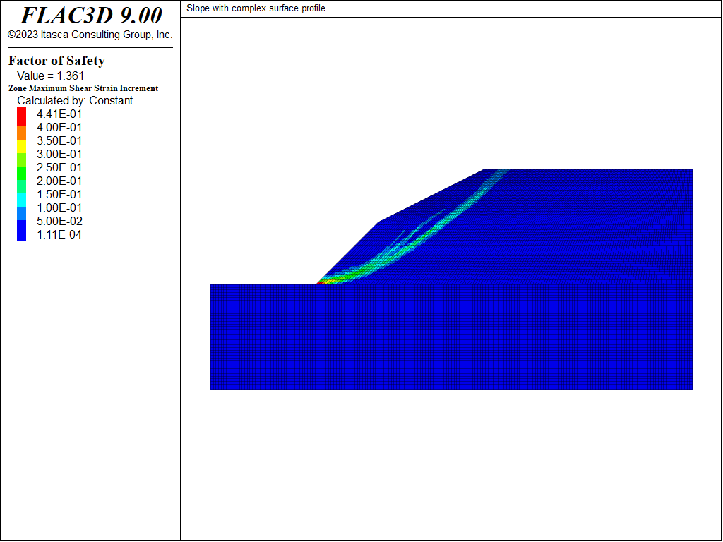
Figure 5: Factor of safety results.
Reference
Cheng, Y.M., T. Lansivaara and W.B. Wei “Two-dimensional slope stability analysis by limit equilibrium and strength reduction methods,” Computers and Geotechnics, 34, 137-150, 2007.
Data File
ComplexSlope.dat
;-------------------------------------------------------------
;          complex surface profile in Mohr-Coulomb material
;-------------------------------------------------------------
model new
model large-strain off
fish automatic-create off
model title 'Slope with complex surface profile'
; create model
zone create brick point 0 0,0,0   point 1 10,0,0  point 2 0,0.25,0   ...
                                  point 3 0,0,10  size 40,1,40
zone create brick point 0 10,0,0  point 1 46,0,0  point 2 10,0.25,0  ...
                                  point 3 10,0,10 size 144,1,40
zone create brick point 0 10,0,10 point 1 46,0,10 point 2 10,0.25,10 ...
                                  point 3 16,0,16 point 4 46,0.25,10 ...
                                  point 5 16,0.25,16 point 6 46,0,16 ...
                                  point 7 46,0.25,16 size 144,1,24
zone create brick point 0 16,0,16 point 1 46,0,16 point 2 16,0.25,16 ...
                                  point 3 26,0,21 point 4 46,0.25,16 ...
                                  point 5 26,0.25,21 point 6 46,0,21 ...
                                  point 7 46,0.25,21 size 144,1,20
zone face skin ; Label model boundaries
; initialize gravity
model gravity 10
; assign Mohr Coulomb model and properties
zone cmodel assign mohr-coulomb
zone property density 2000.0 young 1.4e7 poisson 0.3 ...
              friction 30 cohesion 10000.0 tension 1e10
; boundary conditions
zone face apply velocity-normal 0 range group 'East' or 'West'
zone face apply velocity-normal 0 range group 'North' or 'South'
zone face apply velocity (0,0,0) range group 'Bottom'
model save 'initial'
; Solve to initial equilibrium
model solve elastic ratio-local 5e-3
model save 'slope-1'
model factor-of-safety bracket 1.30 1.45 ratio-local 5e-3 filename 'FOS-slope'
| Was this helpful? ... | Itasca Software © 2024, Itasca | Updated: Nov 12, 2025 |
