Liner-Reinforced Beam
Problem Statement
Note
To view this project in FLAC3D, use the menu command . The main data files used are shown at the end of this example. The remaining data files can be found in the project.
A simply supported wooden beam (\(E\) = 8.6 GPa, \(\nu\) = 0, length of 2.5 m, cross-section of 45 by 90 mm) has a concentrated load of 2000 N applied at its center. The beam is modeled with 40 FLAC3D zones. (Note that more zones are required to obtain the correct beam-theory solution. The system, as modeled, is too stiff; however, it is sufficient for the present example.) The FLAC3D model and the displacement field are shown in Figure 1.
The problem is rerun with a 10 mm thick steel liner (\(E\) = 200 GPa, \(\nu\) = 0.3) attached to the beam bottom. By setting the liner cohesive strength to a large value, no slip is allowed to occur at the liner-beam interface. (The liner stiffnesses are chosen using the liner-stiffness equation.) The displacement field of the liner-reinforced beam is shown in Figure 2. The presence of the liner has reduced the maximum mid-span deflection from 9.4 to 5.4 mm. Shear stresses have developed along the liner-beam interface (see Figure 3), and the maximum tensile \(xx\)-stress at the outer fiber of the liner is approximately 35 MPa (see Figure 4). The maximum tensile \(xx\)-stress at the liner mid-surface is 35 MPa. By setting the liner cohesive strength to zero, slip is allowed to occur along the liner-beam interface. The interface shear stresses go to zero, and the displacement field increases to almost match that of the unlined beam (see Figure 5). The liner continues to provide some stiffness to the composite system.
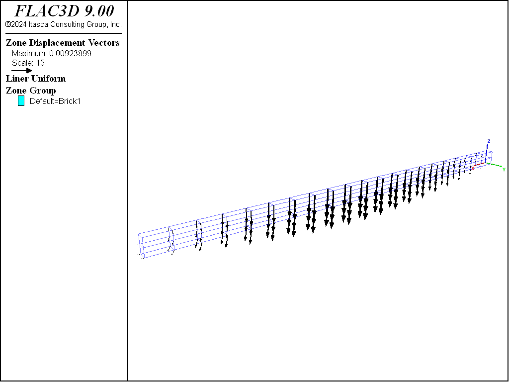
Figure 1: Displacement field of unlined wooden beam.
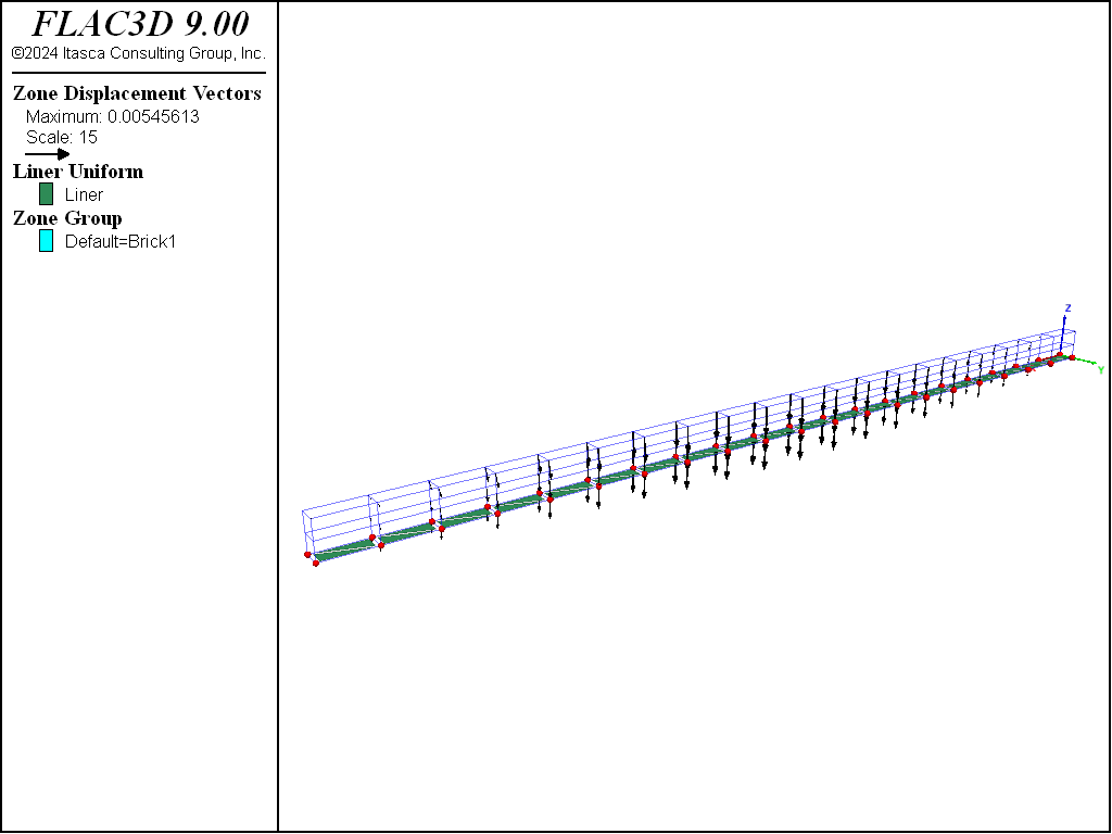
Figure 2: Displacement field of liner-reinforced wooden beam (no slip at liner-beam interface).
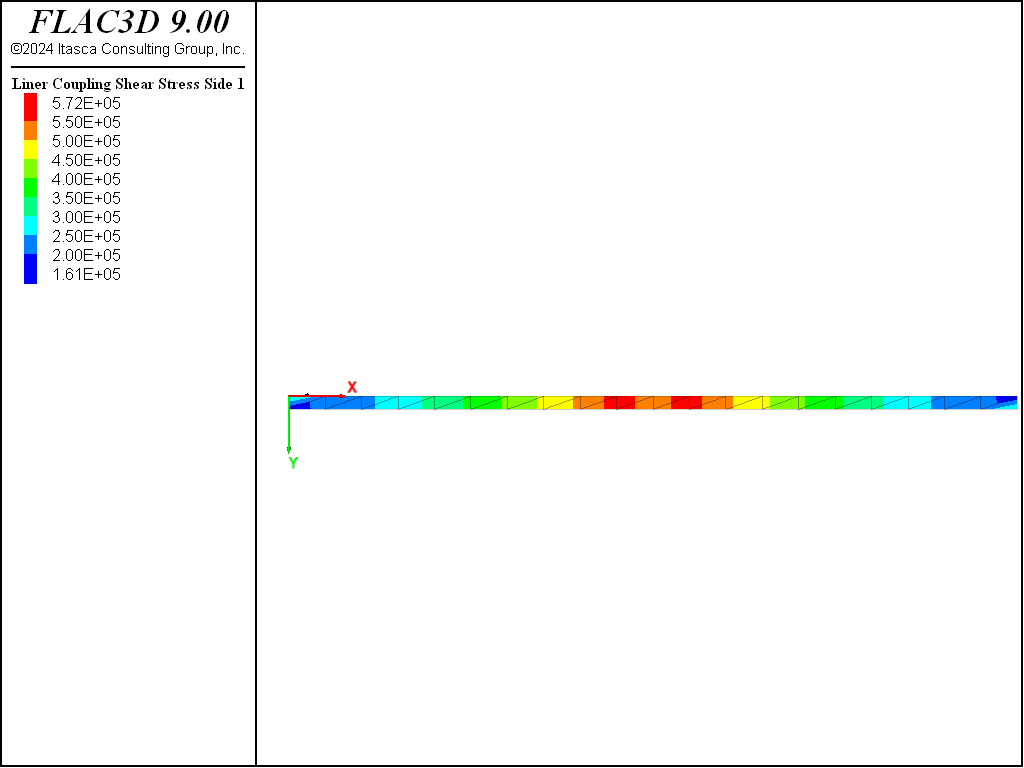
Figure 3: Shear stresses acting on the liner (no slip at liner-beam interface).
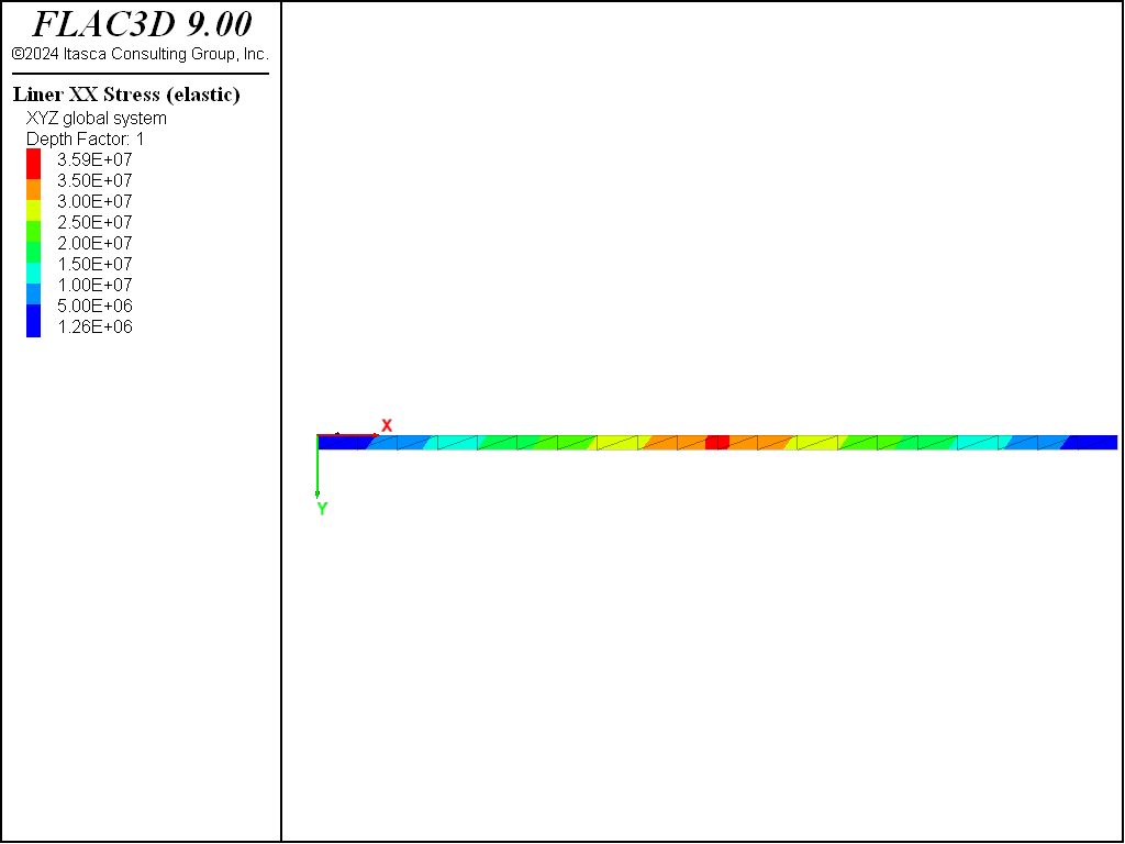
Figure 4: xx-stress carried in the outer fiber of the liner (no slip at liner-beam interface).
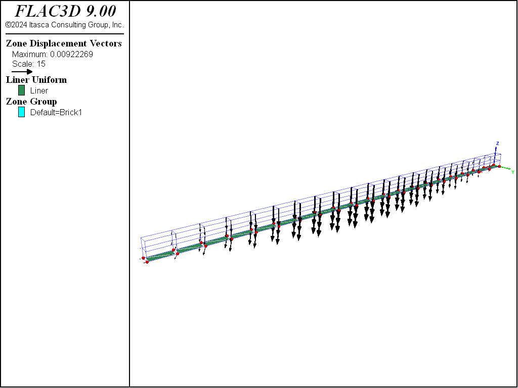
Figure 5: Displacement field of liner-reinforced wooden beam (full slip at liner-beam interface).
We illustrate the effect of mesh configuration when connecting liner elements to the FLAC3D grid by
rerunning this example, but generating a cross-diagonal mesh by adding the keyword cross-diagonal
to the structure liner create command. The bending stress resultant field is shown for the two
different mesh types in Figure 6 and Figure 7. It can
be seen that a near-zero bending moment is occurring at the center of each zone face for the
cross-diagonal mesh that has a node at the face center, whereas this anomaly is absent for the crosshatch
mesh. The reason for this behavior is described in the structure liner create command reference,
and will be repeated here.
When connecting elements to the grid, it is best to locate nodes at gridpoints. If the finite-element type can resist bending (DKT, DKT-CST or DKT- (CST Hybrid) elements), then incompatibilities can develop along element faces and zone faces, because the transverse (out-of-plane) displacement field varies cubically across element faces, but varies only linearly across zone faces. Thus, when connecting bending-resistant elements rigidly to zone faces, it is best to utilize a crosshatch mesh, because the middle node of the cross-diagonal mesh will be constrained to translate according to the linear displacement field of the zone face. This overconstrains the elements and can produce near-zero moments at these mid-nodes when present in a nonzero moment field.
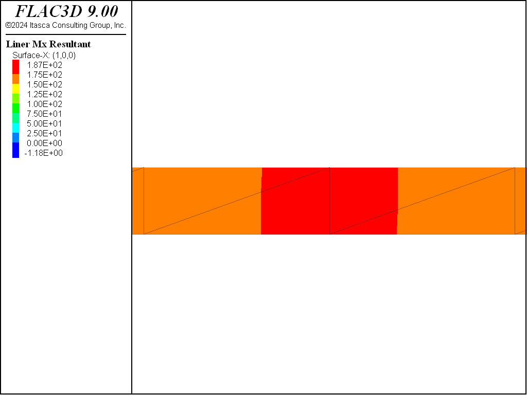
Figure 6: Bending stress resultants, \(M_x\), near liner center (crosshatch mesh).
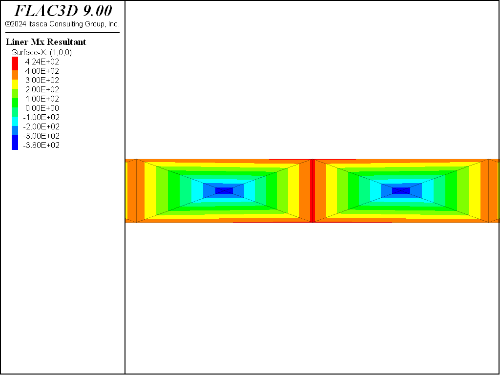
Figure 7: Bending stress resultants, \(M_x\), near liner center (cross-diagonal mesh).
Data File
ReinforcedBeam.dat
; SEL Liner example application - Liner Reinforced Beam
model new
model large-strain off
model title 'Bending of a liner'
; Create zone geometry
zone create brick size (20,1,2) ...
                  point 0 (0,0,0)     point 1 (2.5,0,0) ...
                  point 2 (0,45e-3,0) point 3 (0,0,90e-3)
zone face skin
; Constitutive model and properties
zone cmodel assign elastic
zone property young 8.6e9 poisson 0
; Boundary Conditions
zone gridpoint fix velocity-x range position-x 0 position-z 0
zone gridpoint fix velocity-z range position-x 0 position-z 0
zone gridpoint fix velocity-z range position-x 2.5 position-z 0
zone gridpoint fix force-applied-z -1000 ...
               range position-x=1.25 position-z=90e-3
model save 'Start'

; --- Unlined case
model solve convergence 1
model save 'Unlined'

; Lined Case
model restore 'Start'
; Create liner and properties
structure liner create by-zone-face range group 'Bottom'
structure liner cmodel assign elastic
structure liner property young 200e9 poisson 0.3 thickness=10e-3  ; steel
structure liner property coupling-stiffness-normal=1.9e12 ...
             coupling-stiffness-shear=1.9e12 coupling-cohesion-shear=1e20 ...
             coupling-yield-normal=1e20
structure mechanical damping combined-local
model solve convergence 1
model save 'Lined-NoSlip'

; Reduce liner shear strength
structure liner property coupling-cohesion-shear=0.0
model solve convergence 1
model save 'Lined-Slip'

; Recreate liner with cross-diagonal elements
model restore 'Start'
structure liner create by-zone-face cross-diagonal range group 'Bottom'
structure liner cmodel assign elastic
structure liner property young 200e9 poisson 0.3 thickness=10e-3  ; steel
structure liner property coupling-stiffness-normal=1.9e12 ...
             coupling-stiffness-shear=1.9e12 coupling-cohesion-shear=1e20 ...
             coupling-yield-normal=1e20
structure mechanical damping combined-local
model solve convergence 1
model save 'Lined-Cross'
| Was this helpful? ... | Itasca Software © 2024, Itasca | Updated: Nov 12, 2025 |
