Proppant
This section describes the simulation of proppant within fractures in 3DEC and is mostly taken from Detournay et al. (2015).
Introduction
Hydraulic fracturing is a technique used in the oil and gas industry to stimulate production. The fracturing treatment often involves the injection of proppant as a suspension in the fracturing fluid. After the end of injection, the fracture closes onto the proppant, and a conductive conduit is formed to allow the oil/gas to flow productively.
The transport and placement of proppant within the fracture is usually modeled by representing the proppant and fracturing fluid as a mixture, and this is the approach taken in 3DEC. It is assumed that the proppant particles are small compared to the fracture opening, and the proppant in the mixture is given by its volumetric concentration.
The logic takes into account fluid-mechanical coupling and several effects are represented, such as pack-formation (when the concentration reaches a given value, the proppant forms a pack, leaving only the fracturing fluid to flow through), bridging (when the proppant stops if the fracture width is small enough, compared to the particle size), proppant convection (when density gradients cause fluid motion in the fluid loaded with proppant), and settling (when there is a slip in velocity between slurry and proppant, caused by gravity).
Logic Overview
The transport and placement of proppant within the joints in 3DEC joints is modeled by considering that, in the absence of gravity-induced settling, the proppant and fluid move at the same velocity. The logic follows the general approach summarized by Adachi et al. (2007). It is assumed that the proppant particles are generally small compared to fracture width, and that the distribution of proppant in the fracture is given by its volumetric fraction. Also, the only mechanism to account for relative velocities between the proppant and the carrying fluid is gravity-induced settling.
When the proppant volumetric fraction reaches a saturation value, the slurry (mixture of fracturing fluid and proppant) behaves like a porous solid, and the proppant particles conform to a “pack.” Also, if the joint aperture becomes small compared to particle diameter, the mobility of the proppant is inhibited, again forming a “pack” or “bridge.” Thereafter, two effects are considered: first, the proppant pack is able to take the load from the closing fracture (mechanical effect), and second, only the carrying fluid is able to mobilize through the pores of the pack (fluid transport effect).
When settling is allowed to take place, the proppant velocity has an additional vector component, which acts in the direction of gravity, to account for particle settling. The settling rate is proportional to the Stokes’ velocity (under gravity) of a particle of given size in a fluid of given viscosity. Also, an empirical multiplication factor (a function of volumetric fraction) is applied to Stokes’ velocity to account for particle interaction and wall effects.
Basic Equations
The advective (volume conservation) equation for the proppant volumetric fraction, \(C\), is
where \(a\) is joint aperture and \({\bf v}_p\) is the proppant velocity vector.
Coupling Equation (1) and the logic for fluid flow in 3DEC is done via the slurry velocity, \({\bf v}\), which is obtained by solving the existing fluid flow equations and noting that the relation between slurry flow rate, \(\bf q\), (per unit width of the joint) and slurry velocity is:
In case settling is allowed to take place, the proppant velocity is calculated from the slurry velocity using:
where \({\bf v}_s\), the slip velocity, is a vector parallel to the gravity acceleration, \(\bf g\). The magnitude of the slip velocity is calculated from the Stokes equation, and a correction factor (function of the concentration) is applied to take into account the effect of proppant interaction and wall effects:
In Equation (4), \({\bf v}_{stokes}\) is the Stokes’ drag law on a single particle:
where \(\rho_p\) and \(\rho_f\) are the density of the solid particle and the carrying fluid, respectively, \(d_p\) is the representative diameter of the proppant, and \(\mu\) is fluid viscosity.
Also, a widely used form of the correction factor is provided by the Richardson and Zaki correlation (1954):
After substitution of Equation (6) in Equation (4), and of the resulting expression in Equation (3), we obtain:
where
The settling rate coefficient \((1-c)^{5.65}\) is plotted versus volumetric concentration, \(c\) in Figure 1.
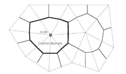
Figure 1: Settling rate coefficient versus concentration.
Proppant Convection
Another coupling variable of interest is the slurry density, which affects the Reynold’s governing equation for the fluid flow. In the proppant logic formulation, the Boussinesq approximation (fluid density variations due to concentration changes are significant only in their generation of buoyancy forces) is invoked.
In the existing 3DEC fluid flow logic, the flow rate per unit width of the joint is:
where \(k=a^2 / (12 \mu)\) is the joint mobility coefficient, \(\rho\) is the fluid (slurry) density and \(g\) is gravity. In the Boussinesq approximation, it is assumed that the fluid density in Equation (6) relates to the proppant concentration, \(c\), by the linear equation:
where \(\rho_f\) is the density of the carrying fluid and \(\rho_p\) is the density of the proppant.
Slurry Viscosity
The coupling between the viscosity of the slurry and fluid flow can be obtained by adjusting the carrying fluid viscosity with the proppant concentration by means of empirical formulae. 3DEC uses the relationship described in Mack and Warpinski (2000)
where \(\mu_{base}\) is the user-input fluid viscosity (block fluid property viscosity), and \(c_{limit}\) is the user-defined concentration limit at which proppant starts carrying load (block fluid proppant concentration-limit-volume). As \(c/c_{limit}\) approaches 1, \(\mu_{slurry}\) approaches infinity, so in 3DEC \(c/c_{limit}\) is set to a maximum value of 0.9.
Slurry viscosity can be plotted ( / / ) and can be queried with FISH (flowplane.vertex.visc).
Numerical Implementation
The advection equation is solved numerically using a node-centered finite volume approach. The scheme takes advantage of the triangular discretization of the flow planes used in the fluid flow calculations. Also, the nodes are discretization features located at the triangle apex. A control domain is assigned to each node, and the proppant volume fraction, \(c\) , the proppant height in the joint, \(h\) , together with the joint aperture, \(a\) , are averaged over the control domain. The boundary of the two-dimensional control domain for a particular node is a polygon of straight line segments; two segments are defined per triangle having the node in common, and each segment links the center of the triangle to the mid-point of a side that radiates from the node, see Figure 2.
The proppant volume fraction at a node (located in a joint) is
and the proppant height at a node is
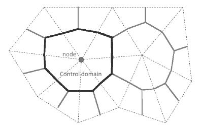
Figure 2: 3DEC flow plane discretization in triangles (dashed) showing node and control domain (solid).
To discretize Equation (1) using the finite volume method, we first integrate over the control domain of area, \(A\):
and then make appropriate approximation for fluxes across the boundary of each control domain.
Transport with No Aperture Change
We examine each term in Equation (14) separately for the case when transport is taking place and aperture is not changing.
Transient Term
When transport is taking place (and aperture is kept constant), the discretization of the transient term integral is given by
where \(\Delta t\) is the timestep.
Advection Term
The advection term is expressed in terms of the slurry and settling velocities using Equation (3):
We use Gauss’ divergence theorem to transform the integral over the control domain into an integral over its polygonal boundary, \(\mathscr{C}\):
where \(n\) is the normal to the boundary pointing out of the control domain.
The slurry diffusion term in Equation (17) is expressed in terms of flow rate per unit width of the joint, using Equation (2):
The discretization of the slurry diffusion term is given by:
where the summation over the boundary segments of a control domain is denoted by \(\sum_s\) and \(L_s\) is the length of each segment.
The vector \({\bf n}\) is the normal to the segment pointing out of the control domain centered on point \(P_1\) into an adjacent control domain centered on point \(P_2\) , see Figure 3. The value of \(c_s\) is determined by the convection scheme adopted to achieve physically realistic solutions. Here, we use an upwind scheme, whereby the advected quantity \(c_s\) is taken upstream from the flow:
The upwind scheme is unconditionally stable; however, the solution over-predicts the diffusive terms producing numerical smearing of the front. The quality of the solution can potentially be improved using second-order correction terms with flux limiters; however, this technique is not implemented in the current version of the scheme.
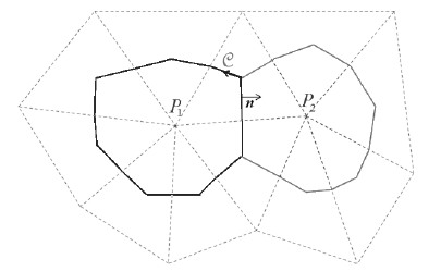
Figure 3: Control domains and quantities used to illustrate the upwind advection scheme.
The settling diffusion term in Equation (17) is a non-linear function of the primary variable, \(c\). The discrete form used in the numerical scheme is given by
where \(h = ca\) (see Equation (13)), the value of \(\overline{c}\) (used to express the correction term \(f^*\)) is the average value of \(c\) at the three nodes of the triangle containing the boundary segment, and
Combining Equations (15), (19), and (21), the discretization of Equation (14) is written for each control domain as
In the (explicit) time stepping numerical scheme, all the quantities in the right-hand side of Equation (23) are assumed to be known from the previous timestep. A new proppant height for the step is evaluated for each node, and the volume fraction is then updated using Equation (12).
The fluid flow scheme already in place assumes fluid volume balance. Also, the advection scheme conserves proppant volume (there is no lost proppant because it is simply moved from control volume to another in the flow domain); this will be demonstrated in the example below.
Mechanical Coupling
Aperture Change with No Transport
In addition to the change in concentration due to advection, the concentration at a node changes with changes in aperture. When no transport is taking place, the advective equation (Equation (14)) simplifies to
The equation implies that the product \(ca\) remains constant. In other words, because the mass of proppant is constant during the mechanical step in which aperture is changed, the new concentration \(c_1\) may be calculated directly from the change in joint aperture (from \(a_0\) to \(a_1\)) during the step as follows:
where \(c_0\) is the concentration before the step.
Load Carried by the Proppant Pack
The condition for proppant taking the load is reached when the proppant (volumetric) concentration reaches the saturated value, \(c_{limit}\), equal to the ratio between maximum initial (unloaded) density of packed proppant, \(\rho_0\), and the density of the proppant particles, \(\rho_p\). The limit is set with the command block fluid proppant concentration-limit-volume.
The general equation for the stress carried by a laterally confined pack of material of maximum initial (unloaded) density, in which an axial displacement, \(\Delta u\), is applied is:
where \(B\) is the confined modulus (equal to \(K + 4G / 3\) for an isotropic material), and \(h_p^*\) is the height of the unloaded pack. The confined modulus for the pack is set using the command block fluid proppant modulus. The relation of fracture width to stress from tests performed on proppant suggests that the assumption of linearity in Equation (26) is valid.
Expressing Equation (26) in incremental form for a fracture of aperture \(a\):
This equation is valid only if the condition for the proppant to take the load has been met (i.e., \(c > c_{lim}\)) and for as long as the total stress, \(\sigma\), remains compressive. If the requirement is not met, the proppant takes no load. The constants \(c_{lim}\) and \(B\) are input properties for the proppant.
If \(\sigma\) > 0 in a particular node, the advection of proppant is blocked. However, the carrying fluid is allowed to flow through the pack; the intrinsic permeability of the pack is a user-input value (block fluid proppant permeability).
The mechanical effect of proppant on the normal contact force, \(F_n\), is captured by the following equation:
where \(\Delta \sigma\) is the change of proppant stress over one timestep, and \(w_f\) is an appropriate node-contact weighting factor.
Bridging
The proppant is blocked if the fracture width is small enough compared to the particle size times some empirical factor (>1). The empirical factor is required to account for the fact that blockage may occur when the aperture is larger than the particle diameter due to the formation of arches or bridges in the fracture.
The particle size and blockage factor are user-input values given by the commands block fluid proppant grains-size and block fluid proppant grains-size-factor, respectively. The grain size factor has a default of 1.
When blockage occurs, proppant convection is stopped, but fluid may still flow by specifying a factor that is multiplied by inherent permeability of the flow zone. The command block fluid proppant permeability-factor is used to give a multiplier (generally less than 1) that will reduce the rate of fluid flow through a blocked flow zone. The default value is 0, meaning that no flow will occur through a blocked zone.
A flow zone is considered blocked if any of the nodes in the zone have an aperture less than the limit.
Proppant Convection
The convection mechanism caused by density variation in the slurry is taken into account in the formulation by locally adjusting the slurry density in the fluid transport equation, according to Equation (10).
Condition at an Intersection Between Flow Planes
The simplified, two-plane configuration represented in Figure 4 is used for the discussion.
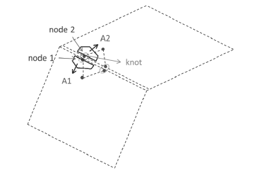
Figure 4: Two intersecting flow planes with discretization triangles, edge nodes, and control domains (dark).
Each flow plane is discretized into triangles; node 1 and node 2, located on the planes intersection, are grouped in a “knot.” The control domains for node 1 and node 2 are lumped together and the result is assigned to the knot:
Also, the knot aperture is evaluated using an area average at the node quantity:
The new proppant height at the knot, \(h_{knot}\), is calculated using the numerical scheme described above; the proppant concentration at the knot, \(c_{knot}\) is then obtained by dividing proppant height by knot aperture, i.e., \(c_{knot} = h_{knot} / a_{knot}\). The knot concentration is assigned to node 1 and node 2, and the new proppant height at the node is computed by multiplying concentration and node aperture \(h_1 = c_{knot} a_1\), \(h_2 = c_{knot} a_2\). The proppant volume balance at an intersection
is conserved automatically using this scheme.
Timestep for Stability
There are two ways to run a fluid-proppant transport calculation: a) uncoupled, where the flow calculation is performed first and the proppant transport next; or b) coupled, where the proppant transport calculation is performed after each flow calculation step.
Also, the stable explicit timestep for the proppant transport is in most cases much larger than the explicit fluid flow timestep.
In uncoupled simulations, the stable timestep for proppant transport is calculated by considering the CFL condition (Courant-Friedricks-Lewy) for the discretized form of the one-dimensional advection equation:
The Courant number is defined in this case as:
where \(\Delta t\) is the proppant timestep and \(\Delta x\) is the discretization length and the condition for stability is
For the 3DEC uncoupled situations, we use the following expression of stable timestep based on Equation (33):
where \(\Delta L_{min}\) is the smallest discretization length, and \(\left | {\bf v}_{p,max} \right |\) is the largest proppant velocity magnitude among triangles in the flow planes.
In coupled simulations, the stable timestep is taken to be the same as the explicit fluid step.
In coupled fluid-proppant-mechanical calculations, in each calculation step, the fluid flow is carried out first, then the proppant transport is done, and finally enough mechanical steps are taken (consistent with the settings) to keep the system in quasi-static equilibrium.
Boundary and Initial Conditions
The proppant concentration in the flow planes can be initialized to a non-zero value using the command flowplane vertex initialize proppant-volume. A range can be given to set up different initial concentrations in different flow planes.
Two types of boundary conditions are considered for the proppant transport problem: imposed volumetric flux of proppant, and imposed volumetric fraction.
The second type is difficult to realize physically; it is introduced only to facilitate potential comparison of the numerical results with existing analytic solutions.
To inject proppant, you can specify the concentration of proppant in the injected fluid using the command flowknot apply proppant-volume. Note that the proppant will not be added (or subtracted) to the system if there is no fluid flow into or out of the grid at the specified boundary location. This means that either a fixed pressure or fluid discharge boundary condition must be applied at the same location as a proppant boundary condition in order for proppant to be injected.
Examples
Planar Flow
A simple advection test is conducted to check the functionality of the proppant transport logic in a planar horizontal joint of constant and uniform aperture. The joint is 10 m long, 1 m wide, and aperture is 0.1 mm. A uniform pressure gradient of 0.1 MPa/m is applied in the long direction of the joint. The fluid viscosity is 10−3 Pa · m. The joint discretization length is 0.25 m. With the parameter values selected for the test, the fluid velocity in the fracture is about 8.33 10−2 m/s, or 1/12 m/s (Figure 5).
Proppant is then injected along the left (short) edge of the joint at a concentration of 0.3. The proppant concentration contours after 60 s are shown in Figure 6. The profiles of concentration at 12 s, 36 s, and 60 s are plotted in Figure 7. The dotted lines show the theoretical proppant front based on the fluid flow velocity. After 12 s, the proppant front is centered approximately along the theoretical line. At later times, the proppant front is slowing down and is falling behind the theoretical lines. This is because the fluid viscosity increases as proppant is injected and the fluid flow slows down. The fluid viscosity and velocity after 60 s are shown in Figure 8. You can see that the viscosity has more than doubled where the proppant concentration is highest, and that the maximum fluid velocity has decreased by about 30%.
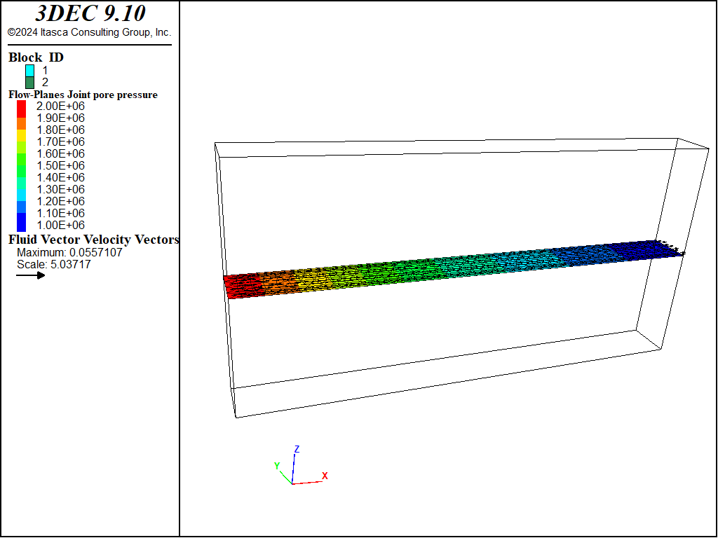
Figure 5: Steady state pore pressures and fluid velocity.
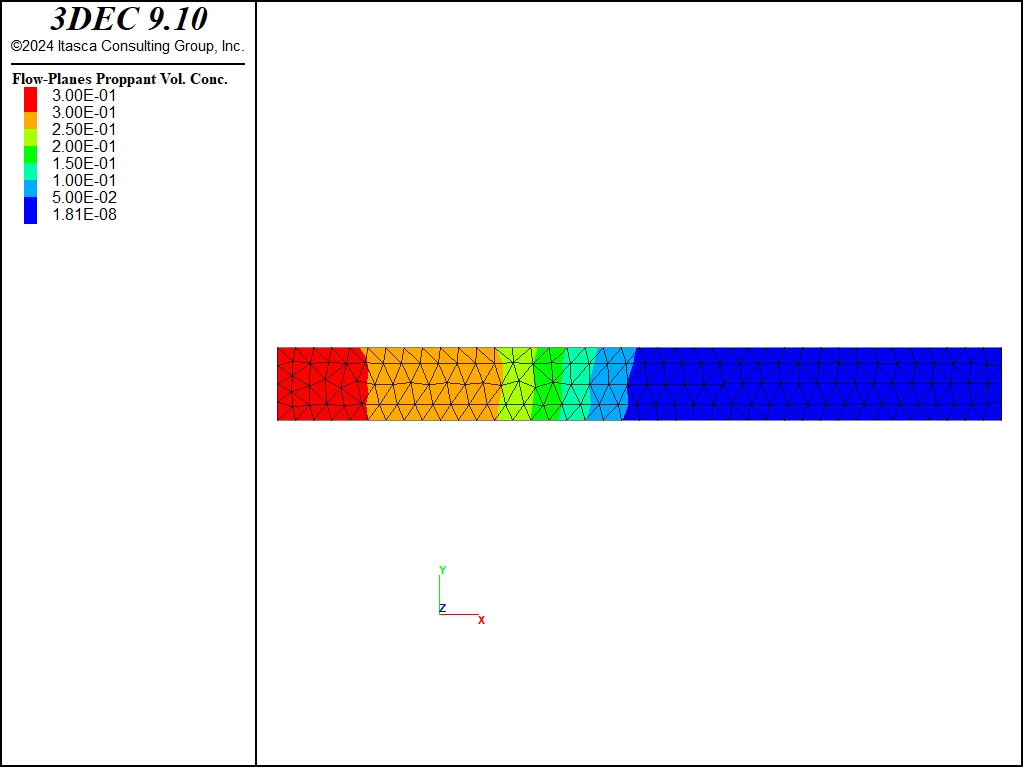
Figure 6: Proppant concentration after 60 s.
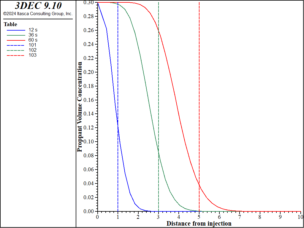
Figure 7: Profiles of proppant concentration along the center of the plot plane at three different times; dotted lines show theoretical front of proppant for a constant viscosity.
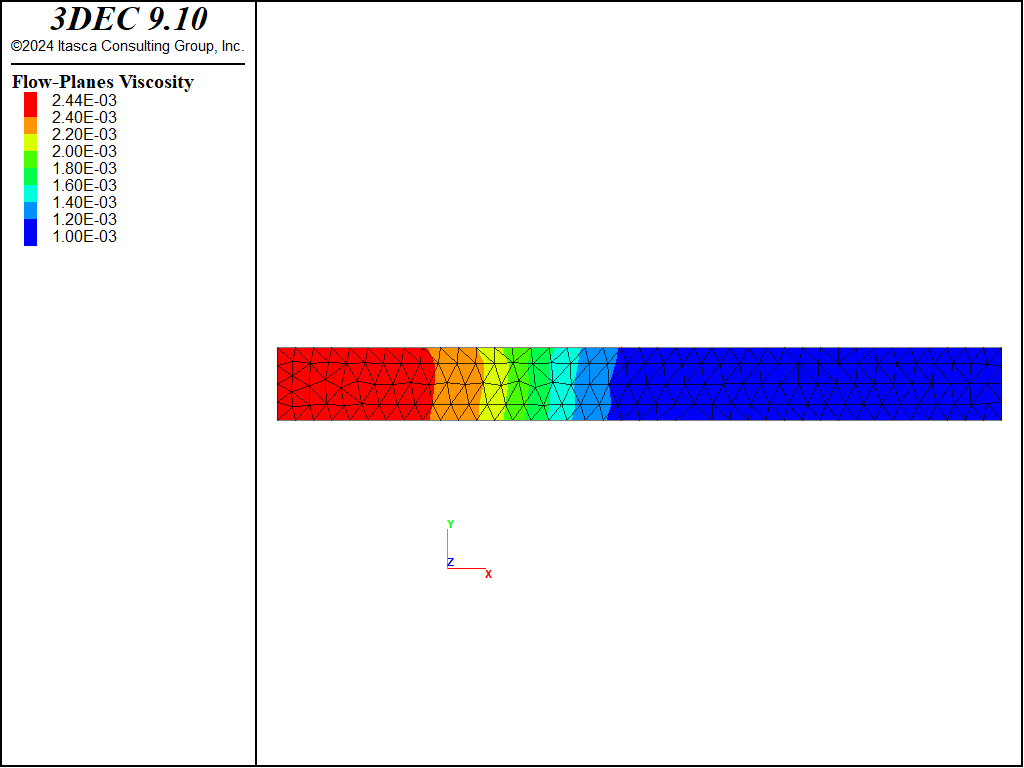
Figure 8: Viscosity and fluid velocity after 60 s.
Data File
model new
model random 10000
model configure fluid-flow
model large-strain off
;
block create brick 0 10 -0.5 0.5 -2.5 2.5
;
block cut joint-set dip 0
;
block zone generate edgelength 0.25
block zone cmodel assign elastic
block zone property density 2500 shear 2e9 bulk 5e9

block contact jmodel assign mohr
block contact property stiffness-normal 5e10 stiffness-shear 1e10

flowplane vertex property aperture-initial 1e-4 aperture-minimum 1e-5 ...
                                                aperture-maximum 2e-4

block fluid property bulk 0.05e9 density 1000 viscosity 1e-3
;
history interval 1000
flowknot history pore-pressure position 0 0 0
flowknot history pore-pressure position 3 0 0
flowknot history pore-pressure position 5 0 0
flowknot history pore-pressure position 7 0 0
;
model fluid active on
model mechanical active off
;
flowknot apply pore-pressure 2e6 range position-x 0 position-z -0.1 0.1
flowknot apply pore-pressure 1e6 range position-x 10 position-z -0.1 0.1
;
; --- cycle to steady-state flow ---
model cycle 20000
;
model save 'advec-ss'
;
; --- now inject proppant
flowknot apply proppant-volume 0.3 range position-x 0 position-z -0.1 0.1
;
block fluid proppant active on
;
model history fluid time
flowplane vertex history proppant-vconcentration position 1 0 0
flowplane vertex history proppant-vconcentration position 3 0 0
flowplane vertex history proppant-vconcentration position 5 0 0
;
model fluid time-total 0
;
fish define profile(itab)
;
; Create profile of proppant concentration along y=0
; Dump to input table itab (integer)

  local tabp = table.get(itab)

  loop foreach local fpx flowplane.vertex.list
    local pos = flowplane.vertex.pos(fpx)
    if math.abs(comp.y(pos)) < 0.1
      table(tabp,comp.x(pos)) = flowplane.vertex.proppan.vconc(fpx)
    end_if
  end_loop

  ; also create a table to show location of theoretical proppant front
  tabp = table.get(itab+100)
  local front = 1.0/12.0*fluid.time.total
  table(tabp,front) = 0.0
  table(tabp,front+0.001) = 0.3
end
;
;
model solve fluid time 12
[profile(1)]
;
model solve fluid time 24
[profile(2)]
;
model solve fluid time 24
[profile(3)]
;
table '1' label '12 s'
table '2' label '36 s'
table '3' label '60 s'

;
model save 'advec-60s'
;
Injection
Fluid injection in a 10 m x 10 m x 10 m block of elastic material containing two perpendicular fracture planes is simulated in this example. The initial stress in the block is 3 MPa in the \(x\)- and \(z\)-directions, and zero in the \(y\)-direction. The first fracture plane is horizontal and goes through the center of the block; the second fracture is vertical and located at \(x\) = 2.5 m. A volumetric source of fluid loaded with proppant is applied at the center of the horizontal fracture plane (note that the range is specified to inject into one and only one flow knot). The volumetric concentration of proppant in the injected fluid is 0.1.
The pore pressure contours and specific discharge vectors in the fractures are shown at the end of the 2 s simulation in Figure 9. The fluid has migrated extensively in the first fracture, and has also intruded in the second fracture. The fracture aperture at 2 s is plotted in Figure 10. Contours of proppant concentration at the end of the 2 s simulation are shown in Figure 11. The simulation shows that the proppant has migrated in a radial pattern in the first fracture, and that it has also intruded in the second fracture. Comparison of the proppant volume injected at the source to the volume of proppant distributed in the model (using a FISH function) shows that volume balance is satisfied to within a relative error less than 0.2% at the end of the simulation.
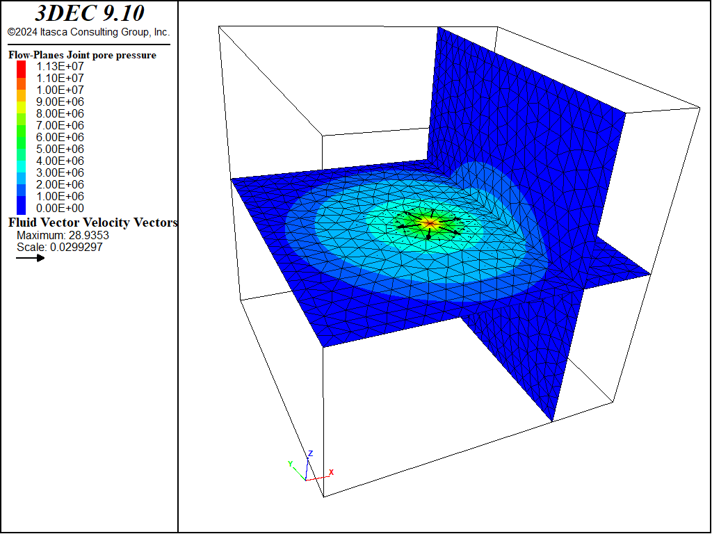
Figure 9: Pore pressures and fluid velocity after 2 s of injection.
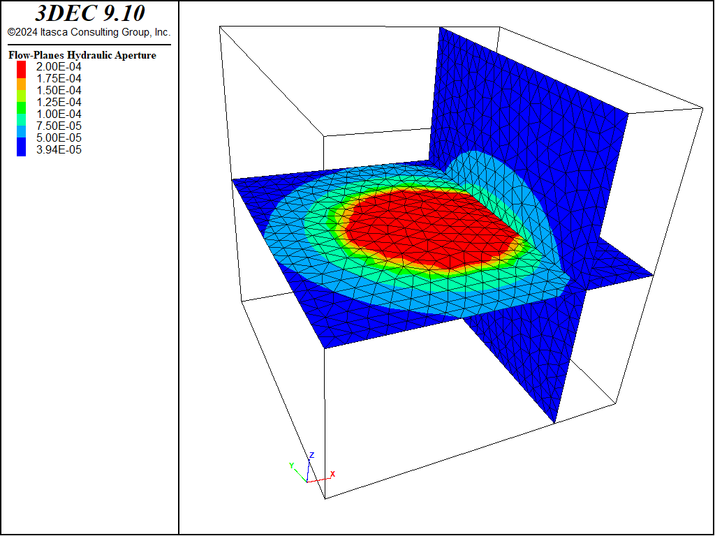
Figure 10: Fracture apertures after 2 s of injection.
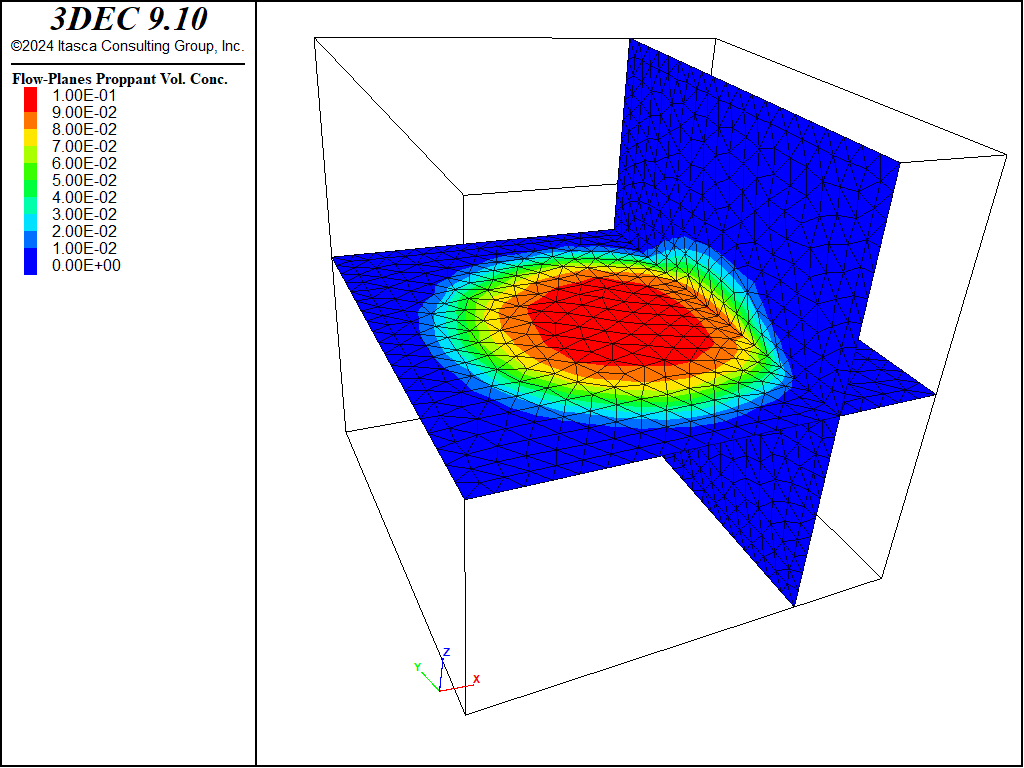
Figure 11: Proppant concentration after 2 s of injection.
Data File
model new
model random 10000
model configure fluid-flow
model large-strain off

block create brick -5 5 -5.0 5.0 -5 5
block cut joint-set
block cut joint-set dip 90 dip-direction 90 origin 2.5 0 0

block zone generate edgelength 0.5

block zone cmodel assign elastic
block zone property density 2500 shear 2e9 bulk 5e9

model save "mesh"

block contact jmodel assign mohr
block contact property stiffness-normal 5e10 stiffness-shear 1e10

flowplane vertex property aperture-initial 1e-4 aperture-minimum 1e-5 aperture-maximum 2e-4

block fluid property bulk 0.05e9 density 1000 viscosity 1e-3

block insitu stress -3e6 0 -3e6 0 0 0
block face apply stress -3e6 0 -3.0e6 0 0 0 range position-z 5
block face apply stress -3e6 0 -3.0e6 0 0 0 range position-x -5
block gridpoint apply velocity-x 0 range position-x 5
block gridpoint apply velocity-x 0 velocity-y 0 velocity-z 0 range position-z -5

block history displacement-x position 0 0 0
block history displacement-y position 0 0 0
block history displacement-z position 0 0 0
flowknot history pore-pressure position -5 0 0
flowknot history pore-pressure position -2 0 0
flowknot history pore-pressure position  0 0 0
flowknot history pore-pressure position  2 0 0
flowplane vertex history proppant-vconcentration position -2 0 0
flowplane vertex history proppant-vconcentration position 0 0 0
flowplane vertex history proppant-vconcentration position 2 0 0

flowknot apply discharge 0.01 ...
               range position-x -0.3 0.2 position-y -0.3 0.3 position-z -0.1 0.1
flowknot apply proppant-volume 0.1 ...
               range position-x -0.3 0.2 position-y -0.3 0.3 position-z -0.1 0.1

model fluid active on
model mechanical active on
block fluid proppant active on

;------------------------
fish define check_volume

  global propp_vol = 0.0

  loop foreach local fpx flowplane.vertex.list
    propp_vol = propp_vol + flowplane.vertex.area(fpx) * ...
                            flowplane.vertex.proppant.thick(fpx)
  end_loop

  ; volume is fluid injection rate x proppant concentration x time
  global volume_inject = 0.01*0.1*fluid.time.total
  local status = io.out('current stayed proppant vol: ' + string(propp_vol))
  status = io.out('actual injected proppant vol: ' + string(volume_inject))
end

model mechanical substep 1
model mechanical follower on
model solve time-total 2.0
[check_volume]
model save "injection"
Bridging
If the fracture is narrower than some small number of particle diameters, then it is likely that a blockage will form, preventing (or reducing) further flow of fluid and proppant. The following example demonstrates this effect.
A flow plane is created with two different properties. Part of the plane is assigned an aperture of 100 \(\mu\)m and the rest has an aperture of 80 \(\mu\)m. After the application of initial stress, the apertures reduce to 40 \(\mu\)m and 20 \(\mu\)m (Figure 12). Fluid and proppant are injected into the wider part of the plane. The model is run uncoupled (fluid flow only).
It is expected that as the fluid front reaches the narrower opening, flow will be restricted. The proppant grain size is set to 10 \(\mu\)m. By default, the grain size factor for bridging is 1 (meaning that if the flow plane aperture is less than 1 × 10 \(\mu\)m, bridging will occur). Since the narrow section of the flow plane has an aperture of 20 \(\mu\)m, bridging is not expected. Figure 13 and Figure 14 show the pore pressure and proppant concentration after 10 s of injection. There is clearly a restriction of flow at the boundary between sections of the flow plane, but fluid and proppant both pass through.
The model was rerun with the grain size factor set to 3, meaning that bridging will occur if the flow plane aperture is less than 30 \(\mu\)m. The permeability factor for the blockage is set to 0.1, meaning that the rate of flow through the blockage will be 10 times less than it would be if there was no blockage.
Figure 15 shows the pore pressures after 10 s of injection. The pressures in the narrow section of the joint are reduced compared to Figure 13. Figure 16 shows the proppant concentration. It is clear that no proppant is passing through the blockage at the transition from wide to narrow aperture.
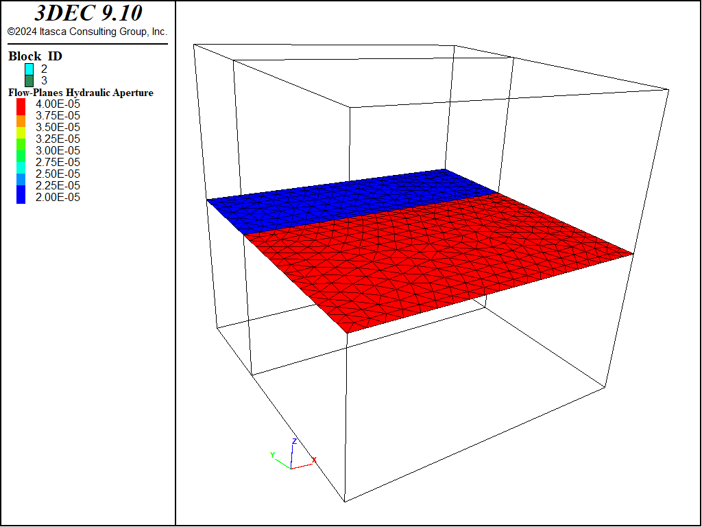
Figure 12: Aperture distribution on the flow plane.
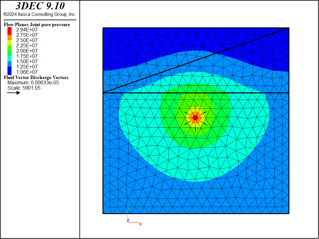
Figure 13: Pore pressures after 10 s of injection with no proppant bridging (grain size factor = 1).
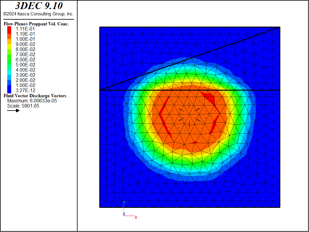
Figure 14: Proppant concentration after 10 s of injection with no proppant bridging (grain size factor = 1).
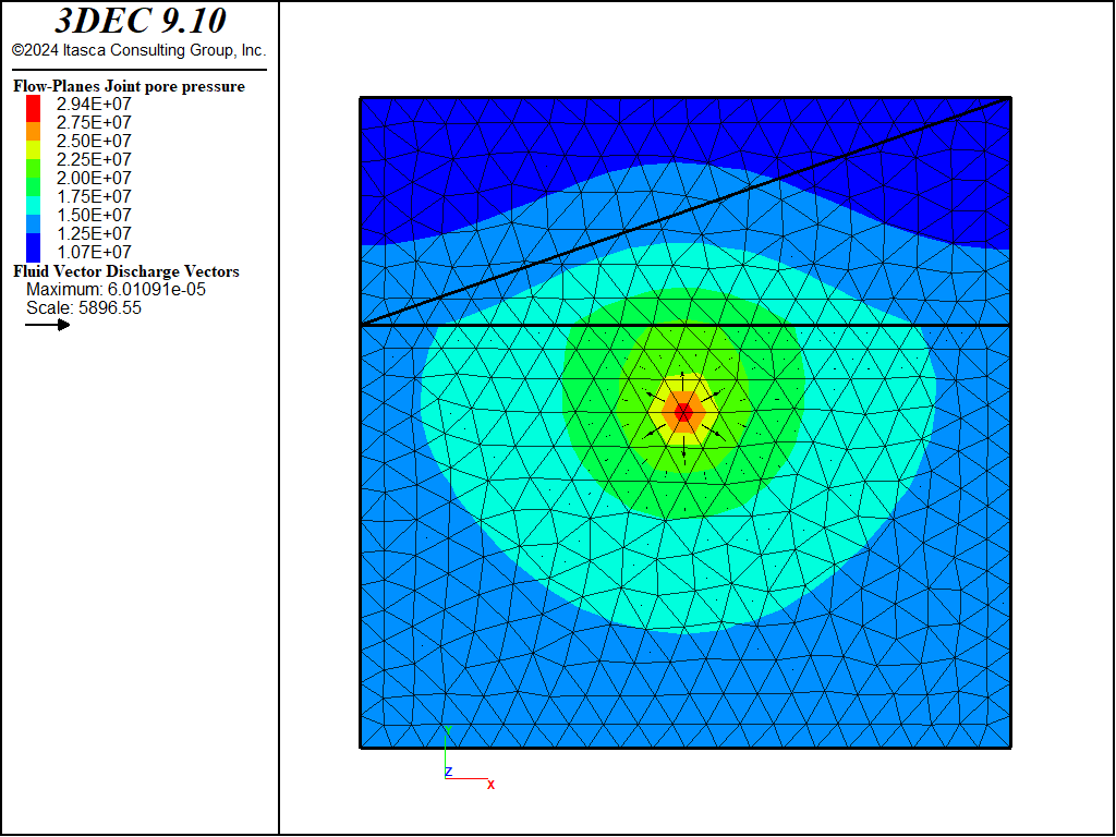
Figure 15: Pore pressures after 10 s of injection with proppant bridging (grain size factor = 3).
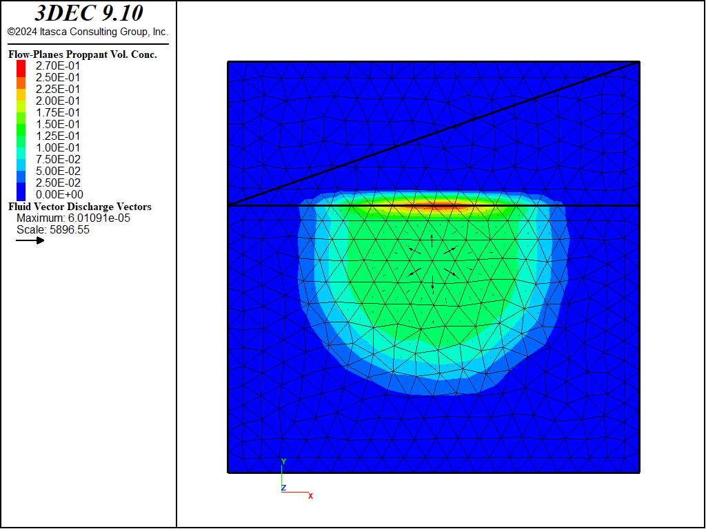
Figure 16: Proppant concentration after 10 s of injection with proppant bridging (grain size factor = 3).
Data File
model new
model random 10000
model configure fluid-flow
model large-strain off

;
block create brick -5 5 -5.0 5.0 -5 5
block cut joint-set dip 90 origin 0 1.5 0
block join
block cut joint-set
;
block zone generate edgelength 0.5
block zone cmodel assign elastic
block zone property density 2500 shear 2e9 bulk 5e9
;
block contact jmodel assign mohr
block contact property stiffness-normal 5e10 stiffness-shear 1e10

; give top  a smaller aperture than bottom
flowplane vertex property aperture-initial 1e-4 aperture-minimum 1e-5 ...
                                                aperture-maximum 2e-4
flowplane hide range position-y -5 1.5
flowplane vertex property aperture-initial 0.8e-4 aperture-minimum 0.8e-5 ...
                                                  aperture-maximum 1.6e-4
flowplane hide off

block fluid property bulk 0.05e9 density 1000 viscosity 1e-3
;
block insitu stress 0 0 -3e6 0 0 0
;
block face apply stress 0 0 -3.0e6 0 0 0 range position-z 5
block gridpoint apply velocity-x 0 velocity-y 0 velocity-z 0 ...
                range position-z -5
;
flowknot history pore-pressure position 0 -5 0
flowknot history pore-pressure position 0 -2 0
flowknot history pore-pressure position 0 0 0
flowknot history pore-pressure position 0 2 0
flowplane vertex history proppant-vconcentration position 0 -2 0
flowplane vertex history proppant-vconcentration position 0 0 0
flowplane vertex history proppant-vconcentration position 0 2 0
;
flowknot apply discharge 0.0001 ...
         range position-x -0.3 0.2 position-y -0.3 0.3 position-z -0.1 0.1
flowknot apply proppant-volume 0.1 ...
         range position-x -0.3 0.2 position-y -0.3 0.3 position-z -0.1 0.1
;
block fluid proppant grain-size 1e-5
block fluid proppant permeability-factor 0.1
;
model fluid active on
model mechanical active off
block fluid proppant active on
;
model save 'bridging-ini'
;
model solve fluid time 10.0
model save 'bridging-factor1'
;
======================================================
;
; now test bridging by increasing particle size factor
model restore 'bridging-ini'
;
block fluid proppant grain-size-factor 3.0
;
model solve fluid time 10.0
model save 'bridging-factor3'
;
program return
;
;
Proppant Settlement
To illustrate the settlement of proppant under gravity, a simple model is presented with a single vertical fracture. The initial pore pressure is set to 5 MPa and fluid (without proppant) is injected at a rate of 0.0007 m2/s along one edge. The pressures after 2 s are shown in Figure 17. In this example, the fluid bulk modulus is set to an unrealistically low value (0.01 MPa) to speed up the solution. Therefore the time is not indicative of real time.
Proppant is then added to the injected fluid at a concentration of 0.1. The proppant is assigned a realistic density (2650 kg/m2) and grain size (0.425 mm) and proppant settling is turned on. A maximum concentration of 0.7 is specified. This means that when the concentration reaches this value, the proppant is closely packed and the concentration cannot increase further. In addition, the permeability will drop, reflecting the constricted flow in these zones. The intrinsic permeability for the proppant pack is set to a low value (5.33 × 10⁻¹³ m2).
The proppant concentration and flow vectors after 20 s and 40 s of proppant injection are shown in Figure 18 and Figure 19, respectively. These figures show how the proppant settles to the bottom of the fracture and forms a “bank” over which the fluid and proppant must flow due to the decreased permeability and restricted proppant flow in this region.
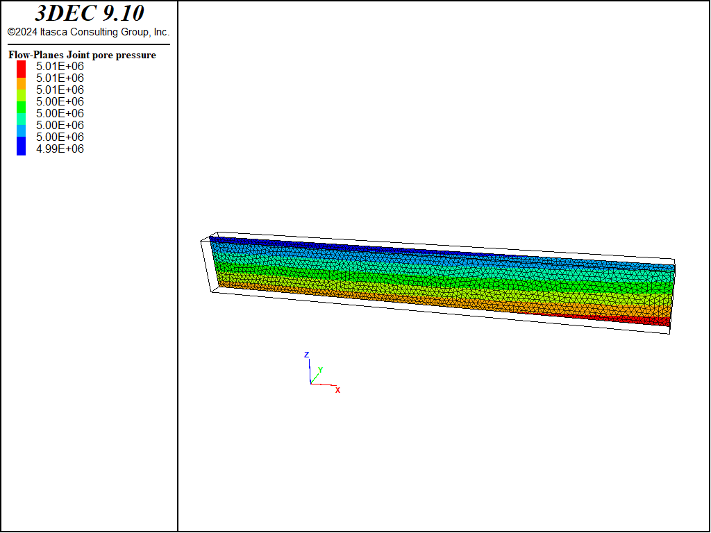
Figure 17: Pore pressures prior to proppant injection.
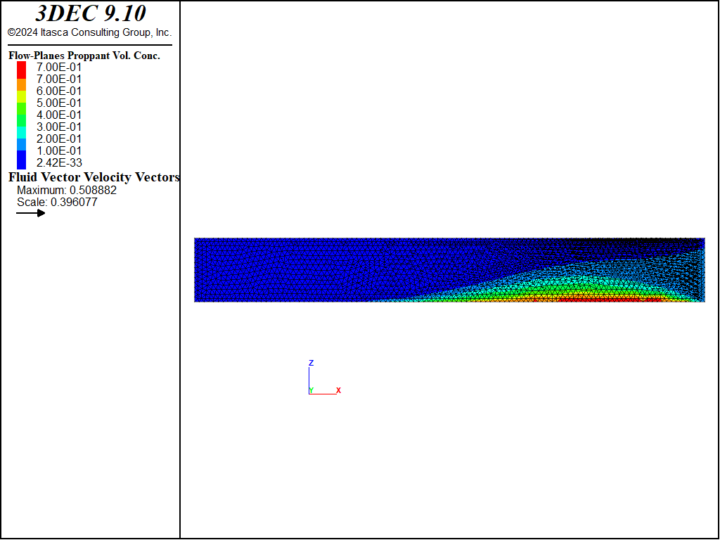
Figure 18: Proppant concentration and flow velocity after 20 s of proppant injection.

Figure 19: Proppant concentration and flow velocity after 40 s of proppant injection.
Data File
model new
model random 10000
model configure fluid-flow
model large-strain off
;
block create brick -4.0 4.0 -0.25 0.25 -0.5 0.5
block cut joint-set dip 90 dip-direction 0
;
block zone generate edgelength 0.075
block zone cmodel assign elastic
block zone property density 2500 shear 2e9 bulk 5e9

model save "mesh"

block contact jmodel assign mohr
block contact property stiffness-normal 5e10 stiffness-shear 1e10
block contact property friction 40 cohesion 0.0 tension 0.0

flowplane vertex property aperture-initial 2e-3 aperture-minimum 2e-3 ...
                                                aperture-maximum 1e-2

; note low fluid modulus to speed up solution
block fluid property bulk 1e4 density 1300 viscosity 1e-3
;
block insitu stress 0 -10.0e6 0 0 0 0 gradient-z 0.0 1.6e4 0.0 0.0 0.0 0.0
block insitu pore-pressure 5.0e6 gradient 0.0 0.0 0.0
;
model gravity 0.0 0.0 -10.0
;
block gridpoint apply velocity 0 0 0 range position-y -0.25
block gridpoint apply velocity 0 0 0 range position-y 0.25
;
history interval 1000
model history fluid time
block history displacement-z position 0 0 0
flowknot history pore-pressure position 0 0 0
;
flowplane edge apply discharge 0.0007 range position-x 4
;
model fluid active on
model mechanical active off
model solve fluid time 2.0
model save 'settlement_ini'
;
;
flowplane vertex history proppant-vconcentration position 0 0 0.5
flowplane vertex history proppant-vconcentration position 0 0 0
flowplane vertex history proppant-vconcentration position 0 0 -0.5
flowplane vertex history proppant-thickness position 0 0 0.5
flowplane vertex history proppant-thickness position 0 0 0
flowplane vertex history proppant-thickness position 0 0 -0.5
;
block fluid proppant concentration-limit-volume 0.7
block fluid proppant permeability 5.33e-13
block fluid proppant grain-size 0.425e-3
;
block fluid proppant density 2.65e3
block fluid proppant settling on
block fluid proppant active on
;
flowknot apply proppant-volume 0.1 range position-x 4
;
model solve fluid time 10.0
model save 'settlement_10s'
;
model solve fluid time 10.0
model save 'settlement_20s'
;
model solve fluid time 10.0
model save 'settlement_30s'
;
model solve fluid time 10.0
model save 'settlement_40s'
;
| Was this helpful? ... | Itasca Software © 2024, Itasca | Updated: Aug 13, 2024 |
