Orientation Conventions
Orientations are associated with planar features such as joints or contacts, and with certain vectors such as princial stress directions. Details of the conventions used in Itasca software are given below.
Planar Features
For joints/faults/discontinuities, orientations are usually expressed in terms of dip and dip direction (in 3D). The meaning of these quantities are shown in Figure 1. The dip is the angle between the maximum slope and a horizontal plane (0 to 90 degrees). The dip direction is the azimuth of the direction of dip as projected to the horizontal (0 to 360 degrees). Note that in Itasca 3D software, the convention is that the positive y-direction is North, so the dip direction is the angle measured clockwise from positive y on the horizontal plane.
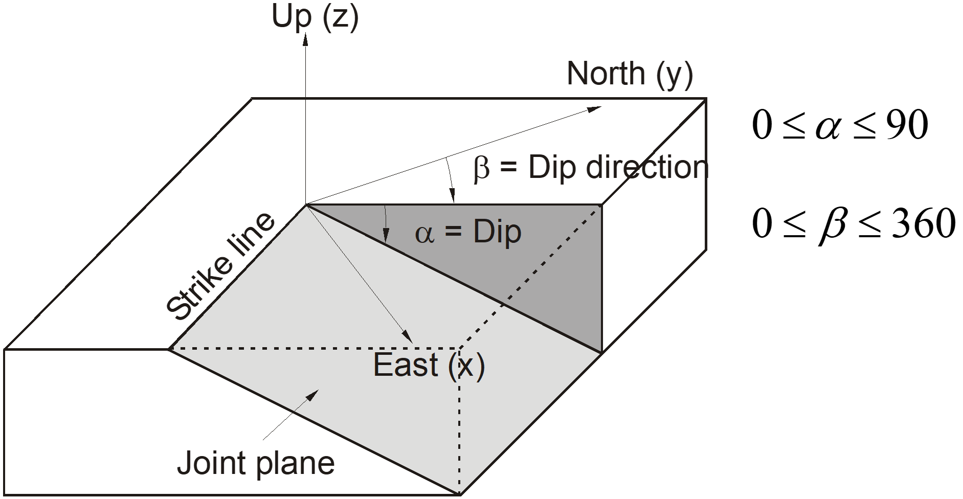
Figure 1: Orientation convention for planar features.
In geology, the term strike is often used to specify the orientation of a plane. Strike is the line representing the intersection of a dipping feature and the horizontal plane. Strike is always 90 degrees to the dip direction.
For planar features, orientation can usually also be given by speciying a normal to the plane. The relationship between normal and dip/dip-direction is
where \(\alpha\) is the dip and \(\beta\) is the dip-direction. A FISH function is provided to do this calculation (math.normal.from.dip.ddir). This function returns a unit vector in the direction of the normal.
When planar features are plotted on a stereonet, Itasca software display the poles to the planes. So, for example, a Discrete Fracture Network with a Fisher distribution of orientations with a mean dip of 30° and dip direction of 10° will show poles as in Figure 2. It is clear that the stereonet is displaying the normals to the planes with the poles plotting at a dip of about 60 and a dip-direction of about 190.
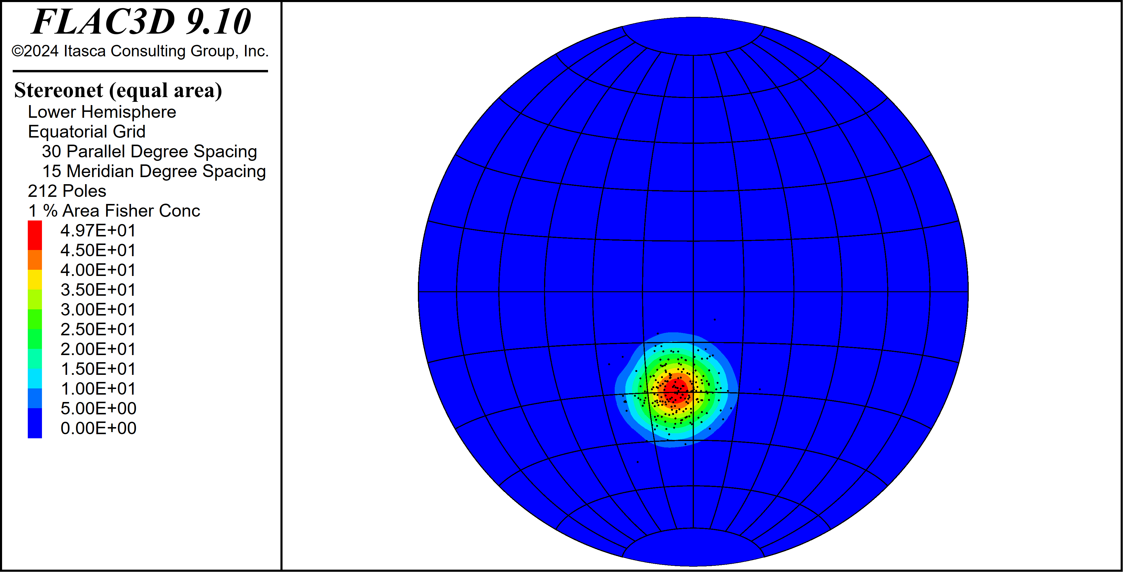
Figure 2: Example distribution of fracture orientations with a mean dip of 30° and dip direction of 10°.
Linear Features
Linear features (such as, for example, maximum principal stress direction) are usually given by a trend and plunge. The plunge is the incliniation of a feature measured downward relative to horizontal (equivalent to dip) and trend is the feature’s azimuth meaured in the direction of plunge (equivalent to dip-direction). In Itasca 3D software, principal stress directions can be given in terms of dip and dip direction (see for example zone.initialize.stress-principal). Principal stress directions can also be given as vectors. Note that the dip and the dip direction are for the vector that defines the stress direction - this is different from planar features where a vector usually defines the normal to the plane. This is illustrated in Figure 3
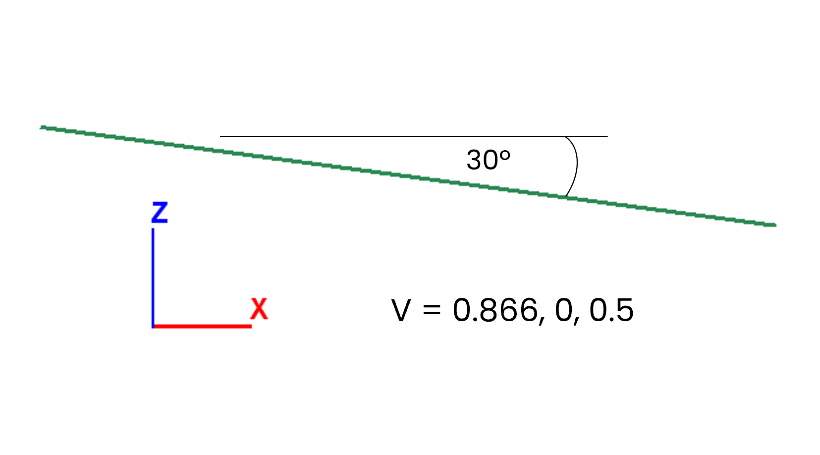
Figure 3: Example linear feature with a dip (plunge) of 30° and a dip direction (trend) of 90°.
When plotted on a stereonet, these features plot the actual dip and dip direction of the vector, rather than a normal as for planes. Figure 4 shows the stereonet for a zone with a maximum stress assigned a dip of 45° and dip direction also of 45°.
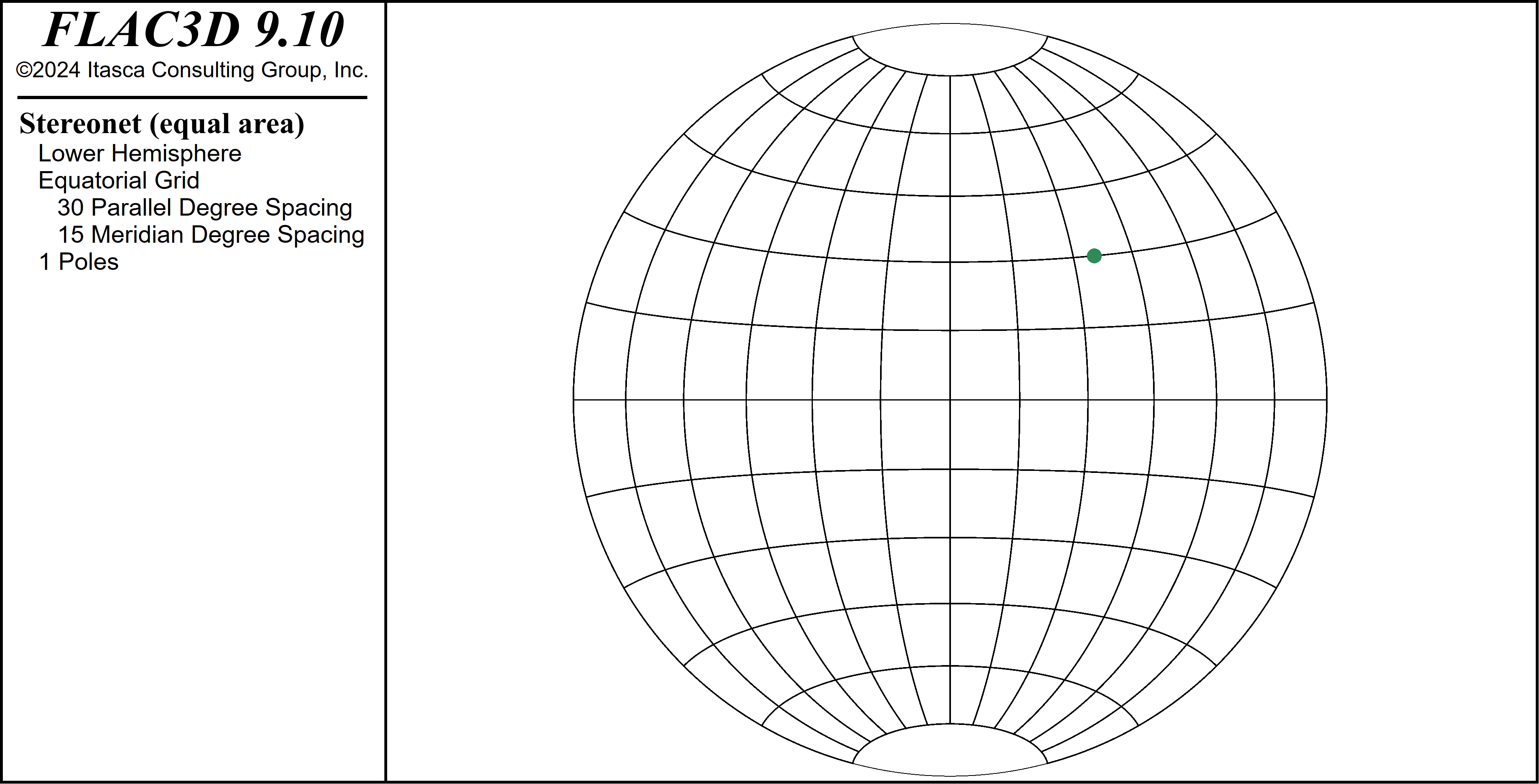
Figure 4: Example linear feature with a dip of 45° and a dip direction of 45° plotted on a stereonet.
A vector can be calculated from trend and plunge as follows:
where \(\alpha\) is the plunge and \(\beta\) is the trend.
| Was this helpful? ... | Itasca Software © 2024, Itasca | Updated: Aug 13, 2024 |
