Creep Response of a Bedded Salt Formation
Problem Statement
Note
The project file for this example may be viewed/run in 3DEC.[1] The project’s main data files are shown at the end of this example.
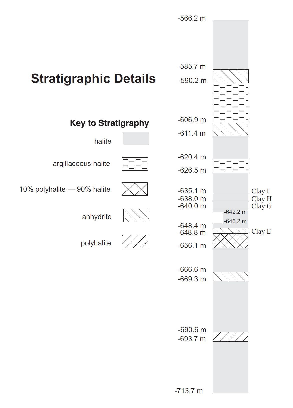
A series of rooms is excavated in bedded salt at a depth of 646 m. A layer of anhydrite is located below the excavations, and clay seams are located above and below the excavations. The stratigraphy is shown in Figure 1, and is based upon stratigraphic information from Morgan et al. (1981). The stratigraphy and excavations reflect those of the Waste Isolation Pilot Plant near Carlsbad, New Mexico.
The objective of the 3DEC analysis is to investigate the time-dependent response of the bedded salt as the rooms are excavated (i.e., room closure). This response will be affected by the presence of the clay layers and the anhydrite layer below the excavation floor.
Different room sizes can be investigated with the 3DEC model. In this example, the rooms are 10 m (33 ft) wide and 4 m (13 ft) high, with room centers 40 m (131 ft) apart. This corresponds to an extraction ratio of 0.25.

Figure 1: Model stratigraphy.
Three bedded salt deposits are defined: halite, argillaceous-halite, and a composite of 10% polyhalite and 90% halite. Both viscoelastic and viscoplastic behaviors are assumed to characterize the time-dependent response of the different salt layers. Non-salt anhydrite and polyhalite layers are also present, and are assumed to behave as Mohr-Coulomb materials. The clay layers are considered weakness planes with a Coulomb shear strength limit. Table 1 and Table 2 summarize the material parameters.
The in-situ stress is lithostatic, with the vertical stress equal to the weight of the overburden material.
Property |
Halite |
b |
Argillaceous-Halite |
b |
10% Polyhalite - 90% Halite |
b |
|---|---|---|---|---|---|---|
Bulk Modulus (GPa) |
20 |
.7 |
20 |
.7 |
22 |
.1 |
Shear Modulus (GPa) |
12 |
.4 |
12 |
.4 |
13 |
.2 |
WIPP contant A |
4 |
.56 |
4 |
.56 |
4 |
.56 |
WIPP constant B |
127 |
.0 |
127 |
.0 |
127 |
.0 |
WIPP constant D |
5 |
.79-35 |
1 |
.74-35 |
5 |
.21-36 |
WIPP exponent n |
4 |
.90 |
4 |
.90 |
4 |
.90 |
Activation energy (cal/mol) |
12000 |
12000 |
12000 |
|||
Crit. s-s creep rate (s-1) |
5 |
.39-8 |
5 |
.39-8 |
5 |
.39-8 |
D-P parameter \(k_{\phi}\) |
5 |
.0 MPa |
||||
D-P parameter \(q_{\phi}\) |
0 |
.5 |
||||
D-P parameter \(q_{\psi}\) |
0 |
.0 |
Property |
Anhydrite |
b |
Clay Seams |
b |
|---|---|---|---|---|
Bulk Modulus (GPa) |
83 |
.4 |
||
Shear Modulus (GPa) |
27 |
.8 |
||
Interface normal stiffness (GPa/m) |
10 |
|||
Interface normal stiffness (GPa/m) |
5 |
|||
Friction angle (degrees) |
29 |
5 |
||
Cohesion (MPa) |
27 |
0 |
.0 |
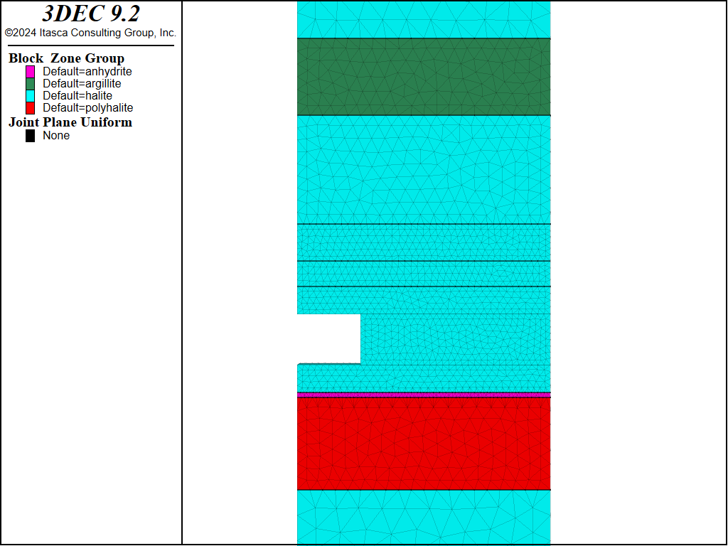
Figure 2 shows the 3DEC model for this example. The regular geometry of the excavations and stratigraphy allows planes of symmetry to be specified vertically through the pillar center (i.e., pillar between adjacent rooms) and the center of a room. The geometry also allows plane-strain conditions to be considered.

Figure 2: 3DEC grid for bedded salt formation (close-up of the excavation).
Planes of symmetry are always planes of zero shear stress. Therefore, the symmetry planes are given roller boundaries. It is important that the upper and lower horizontal boundaries are far enough removed from the excavation to minimize boundary effects of the predicted results. The lower horizontal boundary, while not a plane of symmetry, is assigned roller boundaries. If far enough removed, the effects of fixed or roller conditions for this boundary will be similar. The upper horizontal boundary is specified as a stress boundary, with a vertical stress equivalent to the weight of the material above this boundary.
The WIPP-reference creep model (block zone cmodel assign wipp) is assigned to all salt materials. Four interfaces are created in the model to represent the bedding planes, identified as clay E, clay G, clay H and clay I in Figure 1. Interfaces also exist between the material layers. The material models and interfaces are shown in Figure 2.
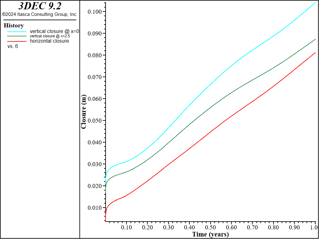
The analysis comprises three stages. In Stage (1) (i.e., prior to room excavation) the model is run to initial equilibrium. In Stage (2), the excavation takes place. This is done instantly, and the model is subsequently run to equilibrium without creep. Because the real-world excavation process is relatively fast, this is a reasonable approach. Only a minimal amount of creep can occur during the short excavation period. In Stage (3), the effect of creep is invoked, and the model ris un for a period of one year. The vertical displacements in the roof and floor, and the horizontal displacement at the springline, are monitored during the one year period.
The room closure is indicated by the convergence history plots in Figure 3.

Figure 3: Room closure histories: vertical convergence at two locations and horizontal convergence at the room mid-height.
Data Files
RoomCreep.dat
model new
; file RoomCreep.dat
; Creep response in a bedded salt formation
;
model configure creep
model large-strain off

block create brick 0 20 0 1 -80 80
; room
block cut joint-set dip 0 dip-direction 0 origin 0 0 -2.2 join
block hide range position-z -2.2 80
block cut joint-set dip 0 dip-direction 0 origin 0 0 -6.2 join
block hide range position-z -80 -6.2
block cut joint-set dip 90 dip-direction 90 origin 5.0 0 0 join
block hide off
;
; geology
;
block cut joint-set dip 0 dip-direction 0 origin 0 0 19.6
block cut joint-set dip 0 dip-direction 0 origin 0 0 13.5
block cut joint-set dip 0 dip-direction 0 origin 0 0 4.9
block cut joint-set dip 0 dip-direction 0 origin 0 0 2.0
block cut joint-set dip 0 dip-direction 0 origin 0 0 0.0
block cut joint-set dip 0 dip-direction 0 origin 0 0 -8.8
block cut joint-set dip 0 dip-direction 0 origin 0 0 -8.4
block cut joint-set dip 0 dip-direction 0 origin 0 0 -16.1
;
; zoning
;
block hide range position-z -16.1 19.6
block zone generate edgelength 2
block hide off
block hide range position-z -8.8 4.9
block zone generate edgelength 1
block hide off
block hide
block hide off range position-z -8.8 -8.4
block zone generate edgelength .3
block hide off
block zone generate edgelength .5
;
block zone group 'halite'
block zone group 'argillite' range position-z 13.5 19.6
block zone group 'anhydrite' range position-z -8.8 -8.4
block zone group 'polyhalite' range position-z -16.1 -8.8
;
; halite properties
;
block zone cmodel assign wipp range group 'halite'
block zone property bulk 20.7e9 shear 12.4e9 density 2300 ...
  activation-energy 12000 constant-a 4.56 constant-b 127 ...
  creep-rate-critical 5.39e-8 constant-gas 1.987 temperature 300 ...
  exponent 4.9 constant-d 5.79e-36 range group 'halite'

;
; --- Anhydrite material properties ---
;
block zone cmodel assign mohr-coulomb range group 'anhydrite'
block zone property bulk 83.4e9 shear 27.8e9 density 2300 friction 29 ...
  cohesion 27e6 range group 'anhydrite'
;
; --- 10% Polyhalite 90% Halite material properties ---
;
block zone cmodel assign wipp range group 'polyhalite'
block zone property bulk 22.1e9 shear 13.2e9 density 2300 ...
  activation-energy 12000  constant-a 4.56 constant-b 127 ...
  creep-rate-critical 5.39e-8 constant-gas 1.987 temperature 300 ...
  exponent 4.9 constant-d 5.21e-36 range group 'polyhalite'
;
; --- Argillaceous Halite material properties ---
block zone cmodel assign wipp range group 'argillite'
block zone property bulk 20.7e9 shear 12.4e9 density 2300 ...
  activation-energy 12000 constant-a 4.56 constant-b 127 ...
  creep-rate-critical 5.39e-8 constant-gas 1.987 temperature 300 ...
  exponent 4.9 constant-d 1.74e-35 range group 'argillite'

;
;
; clay layers
;
block contact property stiffness-normal 1e10 stiffness-shear .5e10 friction 5
block contact material-table default property stiffness-normal 1e10 ...
  stiffness-shear .5e10 friction 5
;

; initial condition
model gravity 0 0 -9.81

; top of model is 566 m below the surface
; assume density of 2300 kg/m3 forigin overlying material
; compressive stresses are negative
[overburden = -2300*566*9.81]
block insitu topography ratio-x 1 ratio-y 1 overburden [overburden]

; boundaries
;
block face apply stress [overburden] [overburden] [overburden] 0 0 0 ...
  range position-z 80
block gridpoint apply velocity-x 0 range position-x 0
block gridpoint apply velocity-x 0 range position-x 20
block gridpoint apply velocity-y 0 range position-y 0
block gridpoint apply velocity-y 0 range position-y 1
block gridpoint apply velocity-z 0 range position-z -80

block history stress-zz position 0 0 0

model creep active off
model solve
model save 'room_creep_bed1'

block delete range position-x 0 5 position-z -6 -2
model solve
model save 'room_creep_bed2'

==========================================================

block gridpoint initialize velocity 0 0 0

model creep active on
model creep timestep starting .001
model creep timestep minimum .001
model creep timestep maximum 21600
model creep timestep automatic

;
; FIsh function to define displacement variables
;
fish define vclo
  local igpt1 = block.gp.near(0,0,-2.2)
  local igpt2 = block.gp.near(2.5,0,-2.2)
  local igpm  = block.gp.near(5.0,0,-4.2)
  local igpb1 = block.gp.near(0,0,-6.2)
  local igpb2 = block.gp.near(2.5,0,-6.2)
  vclo  = block.gp.disp.z(igpb1) - block.gp.disp.z(igpt1)
  global vcloq = block.gp.disp.z(igpb2) - block.gp.disp.z(igpt2)
  global hclo  = -2.0*block.gp.disp.x(igpm)
  global years = creep.time.total/(3600*24*365.25)
end
;
; Histories
;
history interval 1;  200
fish history name 'vertical closure @ x=0' vclo
fish history name 'horizontal closure' hclo
fish history name 'vertical closure @ x=2.5' vcloq
model history creep time-total
fish history years
;
; start creeping
;
model title '5 Days after initial excavation'
model solve time-total 4.32e5
model save 'room_creep_005d'
model title '10 Days after initial excavation'
model solve time-total 8.64e5
model save 'room_creep_010d'
model title '50 Days after initial excavation'
model solve time-total 4.32e6
model save 'room_creep_050d'
model title '100 Days after initial excavation'
model solve time-total 8.64e6
model save 'room_creep_100d'
model title '200 Days after initial excavation'
model solve time-total 1.728e7
model save 'room_creep_200d'
model title '1 year after initial excavation'
model solve time-total 3.15576e7
model save 'room_creep_1_year'
program return
Endnote
| Was this helpful? ... | Itasca Software © 2024, Itasca | Updated: Dec 05, 2024 |
