Example: FOS Calculated for Jointed Rock Slopes
Problem Statement
Note
The project file for this example is available to be viewed/run in in FLAC2D.[1]. The project’s main data files are shown at the end of this example.
Factor-of-safety calculations using the strength reduction method in FLAC2D can determine both the safety factor and the mode of failure of a slope in a jointed rock mass. Several models are run in this example to illustrate the different types of failure modes that can be identified from a factor-of-safety calculation. Modes of failure include rock mass failure in a homogeneous and unjointed rock slope, plane failure of slopes containing either daylighting or non-daylighting discontinuities, and block and flexural toppling failure involving either forward or backward toppling of blocks. (These slope models and modes of failure are also described in detail by Lorig and Varona [2004].)
A simple slope geometry is used for all of the stability analysis cases described in this example. The slope has a height of 260 m and slope angle of 55°. The rock in the model is represented as deformable Mohr-Coulomb material, and the discontinuities behave as Coulomb joint material. The model slope geometry used for all cases is shown in Figure 1.

Figure 1: Slope geometry.
Six slope stability cases are analyzed. The cases include one model with no joint structure, three models with one joint set, and two models with two joint sets. The rock properties and joint properties for the six cases are listed in Table 1.
Soil Property |
Case 1 |
Case 2 |
Case 3 |
Case 4 |
Case 5 |
Case 6 |
|---|---|---|---|---|---|---|
Rock Density (kg/m3) |
2660 |
2660 |
2660 |
2660 |
2660 |
2660 |
Rock Bulk Modulus (GPa) |
6.3 |
6.3 |
6.3 |
6.3 |
6.3 |
6.3 |
Rock Shear Modulus (GPa) |
3.6 |
3.6 |
3.6 |
3.6 |
3.6 |
3.6 |
Rock Cohesion (kPa) |
675 |
675 |
675 |
675 |
675 |
1010 |
Rock Tension (kPa) |
0 |
0 |
0 |
0 |
0 |
1010 |
Rock Friction (degrees) |
43 |
43 |
43 |
43 |
43 |
43 |
Joint Set 1 Dip (degrees) |
– |
35 |
70 |
-70 |
-70 |
55 |
Joint Set 1 Spacing (m) |
– |
20 |
20 |
20 |
20 |
10 |
Joint Set 1 Friction (degrees) |
– |
40 |
40 |
40 |
40 |
40 |
Joint Set 1 Cohesion (kPa) |
– |
100 |
0 |
0 |
0 |
0 |
Joint Set 1 Stiffness (GPa/m) |
– |
1 |
1 |
1 |
1 |
1 |
Joint Set 2 Dip (degrees) |
– |
– |
– |
– |
20 |
0 |
Joint Set 2 Spacing (m) |
– |
– |
– |
– |
30 |
40 |
Joint Set 2 Friction (degrees) |
– |
– |
– |
– |
40 |
40 |
Joint Set 2 Cohesion (kPa) |
– |
– |
– |
– |
0 |
0 |
Joint Set 2 Stiffness (GPa/m) |
– |
– |
– |
– |
1 |
1 |
The cases illustrate six different failure conditions. They are discussed separately below. The command listings for the six cases are given below.
Model Building
Each model is built using i Sketch. Edges are created to represent the joints using the joint-set wizard and they are assigned group names. The grouped edges are then turned into Zone Joints using the procedures described below.
Case 1 - Unjointed Slope
Create a new Sketch Set. Select the Slope Wizard and create a slope as shown in Figure 2. Note that the Slope angle is automatically calculated when the Rise and Run are entered.

Figure 2: Slope Wizard entries for creating the basic slope geometry.
Delete the vertical line at x=398 and the point on the bottom at 398,0. Also delete the vertical line at x=582 and the point at 582,0. Now redraw the bottom horizontal line.
The internal lines are useful for creating a structured mesh for a simple slope, but since most of our slopes will be jointed, these internal lines aren’t necessary.

Figure 3: Edges making up the unjointed slope.
Specify a zone length of 15 and Mesh All Polygons.

Figure 4: Unjointed slope after zoning.
Create the zones and save the state. It is also a good idea to go to the State Record tab, right-click and .
Case 2 - Daylighting Joints
Start with the Sketch from Case 1. Remove the existing mesh by selecting the tool.
For Case 2, joints are dipping at 35° with a spacing of 20 m. To create the joints, we will use the joint-set wizard. Open the joint set wizard and under Domain, select Closed Polygon and click inside the slope. Enter an angle of -35 degrees and a spacing of 20 as shown, and click OK.

Figure 5: Joint set wizard for case 2.
The Sketch should appear as in Figure 6

Figure 6: Array of joints.
Now set the zone length to 10, then go to and check the box for . Then click Mesh Now.

Figure 7: Zoned slope model.
Create the zones and save the state. If building on top of Case 1, delete the existing zones to construct Case 3 (and again for Case 4).
Cases 3 to 6
The procedure for creating the other jointed slopes is similar to that shown above. For Case 5, start with Case 4 and add the second joint set. It will be necessary to select All Polygons for the Domain in this case.
Running the Factor of Safety Analysis
Once each model is constructed, a data file is created. The saved state is restored, properties and boundary conditions are assigned with commands as shown in the data files at the end of this example.
Creating the Zone Joints makes use of the fact that the joint set generator assigns group names to all joints in slot ‘Joint-Set’, allowing use of the command zone joint create by-slot as shown below. The keyword separate is used to separate the faces and create duplicate nodes.
; create joints
zone joint configure
zone joint create by-slot 'Joint-Set' separate

; joint properties
contact property stiffness-normal 1e9 stiffness-shear 1e9 ...
  friction 40 cohesion 1e5 cohesion-residual 1e5
Properties are then assigned to the joints.
During the factor of safety analysis, explicitly include the joints so that their cohesion and friction is reduced in the same way as the cohesion and friction of the zones, e.g.,
model factor-of-safety zone-joint include 'cohesion' ...
  zone-joint include 'friction'  filename 'case2'
Results
Case 1: Unjointed, homogeneous rock – rock mass failure
For Case 1, the slope is a homogeneous rock without joints. Failure of the slope primarily involves shearing though the rock mass, and the shear failure surface is approximately circular as shown in Figure 8. For the Case 1 rock properties listed in Table 1, a factor of safety of 1.73 is calculated. Note that the failure surface in a FLAC2D model can usually be most clearly identified from a plot of velocity vectors and either a displacement contour plot or a velocity contour plot. In Figure 8 velocity vectors and velocity contours clearly show the failure surface.
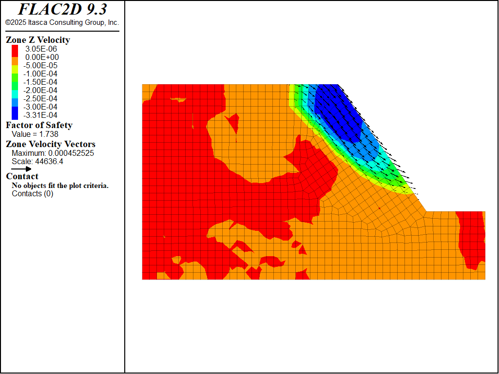
Figure 8: Case 1 — rock mass failure.
Case 2: Daylighting joint structure — plane failure
In the Case 2 simulation, a single joint set is added to the model. The joints dip at 35° and are spaced at 20 m. The failure mechanism that develops combines sliding along joints near the slope toe with tensile failure of the blocks near the top of the slope. Figure 9 shows the failure surface. The calculated factor of safety is 1.27 for this case. Compare to the analytical solution of 1.32 for rigid blocks (Lorig and Varona, 2004).
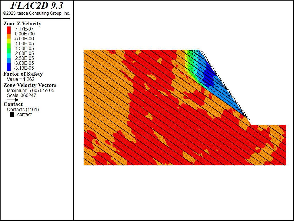
Figure 9: Case 2 — plane failure in slope with daylighting joints.
Case 3: Non-daylighting joint structure — plane failure
In the third case, the dip angle of the single joint set is set to 70° in the same direction as the slope. This produces non-daylighting joints along the slope face. The joint spacing is 20 m. The failure mode that develops in this case involves sliding along the discontinuities, and shearing through the rock blocks at the toe of the slope. Figure 10 illustrates the failure mechanism. The resulting factor of safety is 1.57 for the given problem conditions.

Figure 10: Case 3 — plane failure in slope with non-daylighting joints.
Case 4: Joints dipping into the slope — flexural toppling failure
The joint set is oriented at a dip angle of 70° into the slope and spaced at 20 m in this case. This results in joints dipping steeply into the slope face. The joints form columns that tend to bend out of the slope, and result in a flexural toppling failure mode. Figure 11 shows the failure surface, and Figure 12 illustrates the flexural toppling mode from a magnified view of the block deformation. The calculated factor of safety is 1.24.
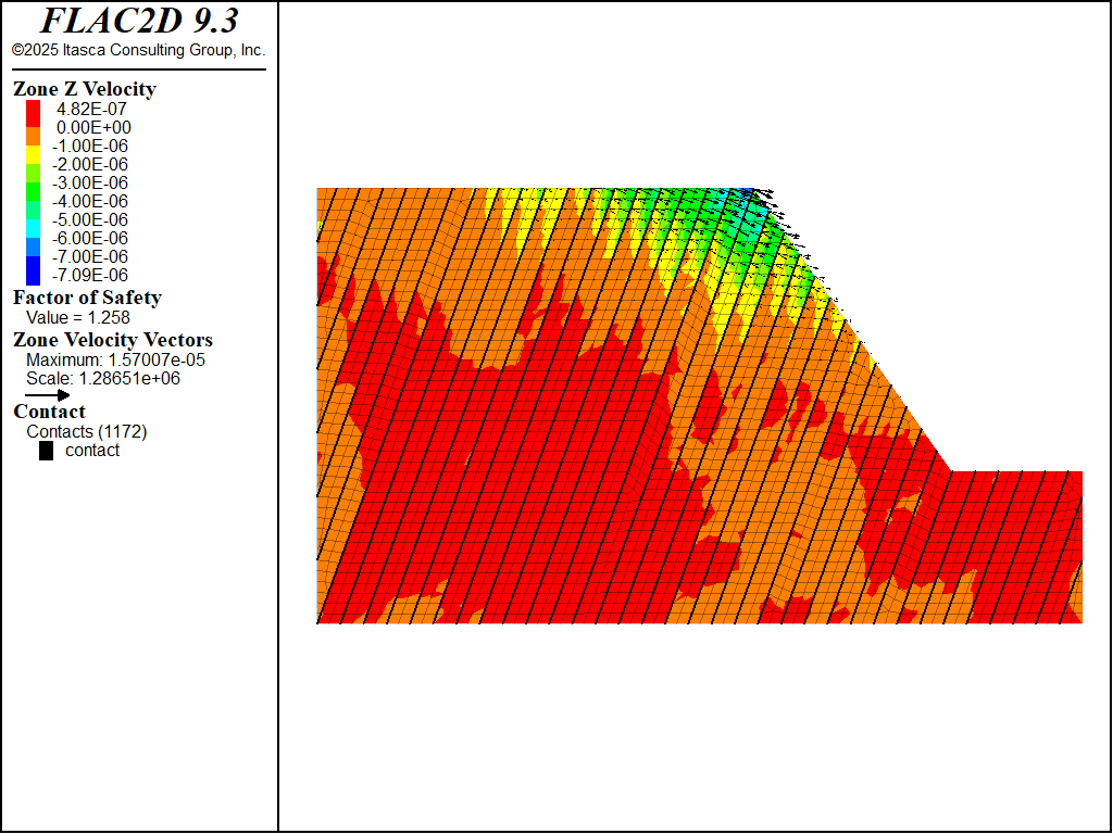
Figure 11: Case 4 — flexural toppling failure for joints dipping into the slope.
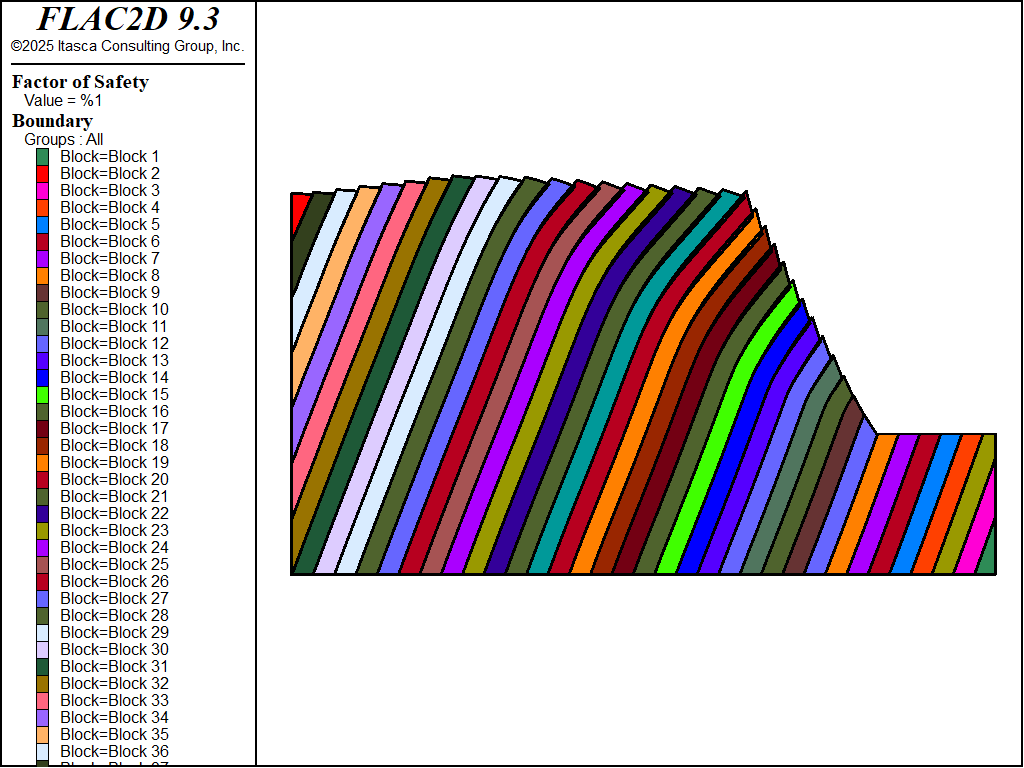
Figure 12: Case 4 — flexural toppling mode identified from magnified block deformation.
Case 5: Two orthogonal joint sets — forward block toppling failure
The slope contains two orthogonal joint sets in Case 5. One set dips at 70° with a spacing of 20 m, and a cross-joint set dips at −20° with a spacing of 30 m. The cross-joints provide release surfaces for rotation of the blocks. The blocks, driven by self-weight, rotate forward out of the slope. Figure 13 shows the failure surface for the Case 5 conditions. The calculated factor of safety is 1.1. The magnified block deformation plot in Figure 14 illustrates the forward block rotation out of the slope.
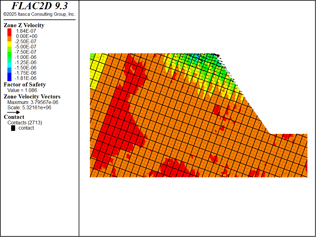
Figure 13: Case 5 — forward block toppling failure for a slope with two joint sets.
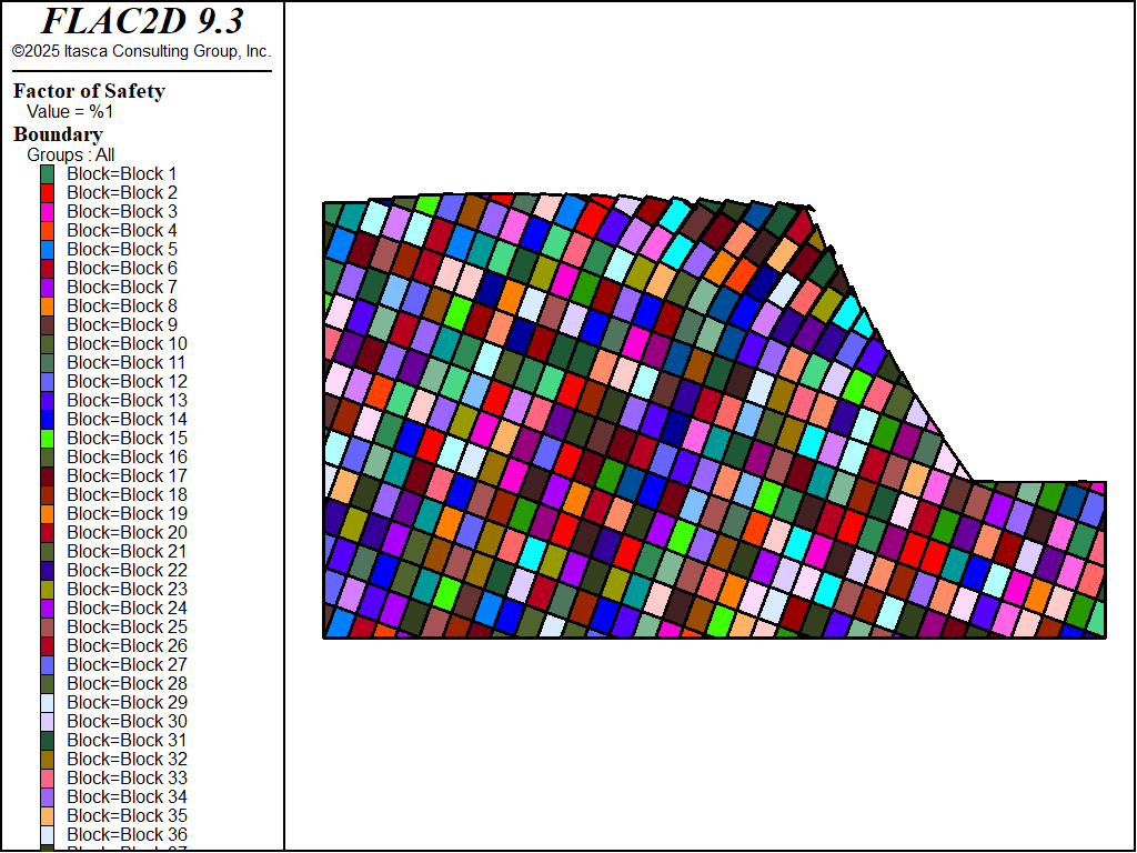
Figure 14: Case 5 — forward block toppling mode identified from magnified block deformation.
Case 6: Two orthogonal joint sets — reverse (backward) block toppling failure
Backward or reverse block toppling failure of a slope can occur when joints parallel to the slope face and flatter cross-joints are particularly weak. In Case 6, one joint set is oriented at 55° (i.e., parallel to the slope face) with a spacing of 10 m. A cross-joint set is horizontal and spaced at 40 m. Note that in this case, in order to highlight the failure mode, elastic material behavior is prescribed for the rock blocks. Figure 15 displays the reverse toppling failure mode. The calculated factor of safety is 1.57. The backward block toppling mode is clearly seen in the magnified block deformation plot in Figure 16.
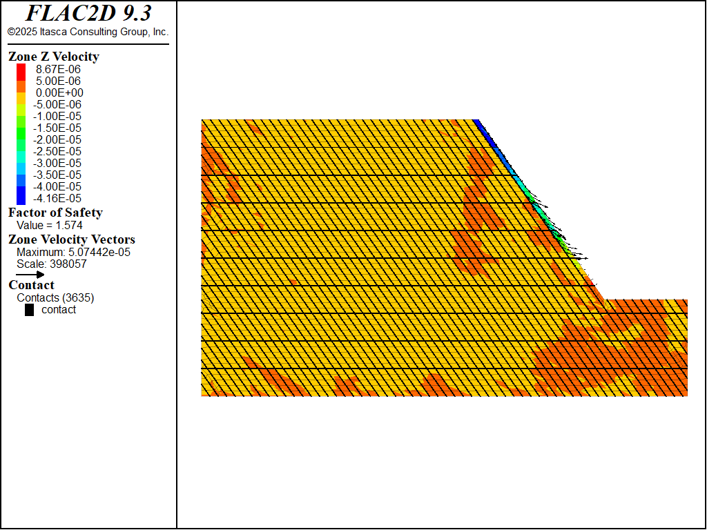
Figure 15: Case 6 — reverse block toppling failure for a slope with two joint sets.
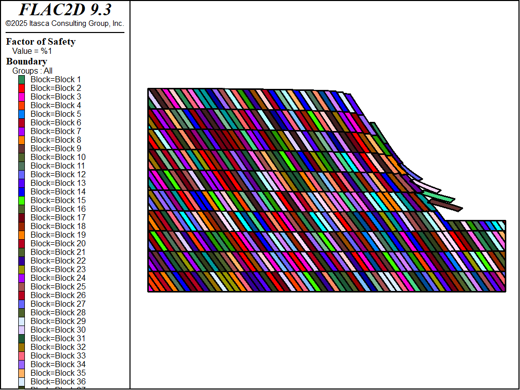
Figure 16: Case 6 — reverse block toppling mode identified from magnified block deformation.
Data Files
case1-run.dat
; Unjointed, homogeneous rock mass
model new
program call 'case1-sketch'

zone cmodel assign mohr-coulomb
zone property density 2660 bulk 6.3e9 shear 3.6e9 cohesion 675e3 friction 43

zone face skin
zone face apply velocity-x 0 range group 'West' or 'East1'
zone face apply velocity 0 0 range group 'Bottom'

model gravity 9.81

model large-strain off
model solve elastic

zone gridpoint initialize displacement 0,0
zone gridpoint initialize velocity 0,0

model factor-of-safety filename 'case1'
case2-run.dat
model new
program call 'case2-sketch'

; create joints
zone joint configure
zone joint create by-slot 'Joint-Set' separate

; joint properties
contact property stiffness-normal 1e9 stiffness-shear 1e9 ...
  friction 40 cohesion 1e5 cohesion-residual 1e5

; zone properties
zone cmodel assign mohr-coulomb
zone property density 2660 bulk 6.3e9 shear 3.6e9 cohesion 675e3 friction 43

; boundary conditions
zone face apply velocity-x 0 range position-x 0
zone face apply velocity-x 0 range position-x 702
zone face apply velocity 0 0 range position-y 0

model gravity 9.81

model large-strain off
model solve elastic

zone gridpoint initialize displacement 0,0
zone gridpoint initialize velocity 0,0

model factor-of-safety zone-joint include 'cohesion' ...
  zone-joint include 'friction'  filename 'case2'
case3-run.dat
model new
program call 'case3-sketch'

; create joints
zone joint configure
zone joint create by-slot 'Joint-Set' separate

; joint properties
contact property stiffness-normal 1e9 stiffness-shear 1e9 ...
  friction 40 cohesion 0

; zone properties
zone cmodel assign mohr-coulomb
zone property density 2660 bulk 6.3e9 shear 3.6e9 cohesion 675e3 friction 43

; boundary conditions
zone face apply velocity-x 0 range position-x 0
zone face apply velocity-x 0 range position-x 702
zone face apply velocity 0 0 range position-y 0

model gravity 9.81

model large-strain off
model solve elastic

zone gridpoint initialize displacement 0,0
zone gridpoint initialize velocity 0,0

model factor-of-safety zone-joint include 'cohesion' ...
  zone-joint include 'friction' filename 'case3'
case4-run.dat
model new
program call 'case4-sketch'

; create joints
zone joint configure
zone joint create by-slot 'Joint-Set' separate

; joint properties
contact property stiffness-normal 1e9 stiffness-shear 1e9 ...
  friction 40 cohesion 0

; zone properties
zone cmodel assign mohr-coulomb
zone property density 2660 bulk 6.3e9 shear 3.6e9 cohesion 675e3 friction 43

; boundary conditions
zone face apply velocity-x 0 range position-x 0
zone face apply velocity-x 0 range position-x 702
zone face apply velocity 0 0 range position-y 0

model gravity 9.81

model large-strain off
model solve elastic

zone gridpoint initialize displacement 0,0
zone gridpoint initialize velocity 0,0

model factor-of-safety zone-joint include 'cohesion' zone-joint ...
  include 'friction'  filename 'case4'
case5-run.dat
model new
program call 'case5-sketch'

; create joints
zone joint configure
zone joint create by-slot 'Joint-Set' separate

; joint properties
contact property stiffness-normal 1e9 stiffness-shear 1e9 ...
  friction 40 cohesion 0

; zone properties
zone cmodel assign mohr-coulomb
zone property density 2660 bulk 6.3e9 shear 3.6e9 cohesion 675e3 friction 43

; boundary conditions
zone face apply velocity-x 0 range position-x 0
zone face apply velocity-x 0 range position-x 702
zone face apply velocity 0 0 range position-y 0

model gravity 9.81

model large-strain off
model solve elastic

zone gridpoint initialize displacement 0,0
zone gridpoint initialize velocity 0,0

model factor-of-safety zone-joint include 'cohesion' ...
  zone-joint include 'friction' filename 'case5'
case6-run.dat
model new
program call 'case6-sketch'

; create joints
zone joint configure
zone joint create by-slot 'Joint-Set' separate

; joint properties
contact property stiffness-normal 1e9 stiffness-shear 1e9 ...
  friction 40 cohesion 0

; zone properties - elastic
zone cmodel assign mohr-coulomb
zone property density 2660 bulk 6.3e9 shear 3.6e9 cohesion 1e20 tension 1e20

; boundary conditions
zone face apply velocity-x 0 range position-x 0
zone face apply velocity-x 0 range position-x 702
zone face apply velocity 0 0 range position-y 0

model gravity 9.81

model large-strain off
model solve elastic

zone gridpoint initialize displacement 0,0
zone gridpoint initialize velocity 0,0

model factor-of-safety zone-joint include 'cohesion' ...
  zone-joint include 'friction' filename 'case6'
Endnote
⇐ Installation of a Triple-Anchored Excavation Wall (FLAC2D) | Fluid Flow Towards a Tunnel (FLAC2D) ⇒
| Was this helpful? ... | Itasca Software © 2024, Itasca | Updated: May 15, 2025 |
